
Imaging reader and method with enhanced aiming pattern detection

a technology of aiming pattern and imager, which is applied in the field of aiming pattern detection, can solve the problems of not being able to read the desired optical code, the aiming pattern cannot be readily detected by the imager module, and the laser beam intensity cannot be increased too much and/or for too long without violating human eye exposure laser safety limits, etc., to achieve the effect of increasing the laser beam intensity, reducing the intensity, and reducing the brightness of both the aiming patterns

Active Publication Date: 2014-12-02
SYMBOL TECH LLC
View PDF44 Cites 2 Cited by
  • Summary
  • Abstract
  • Description
  • Claims
  • Application Information

AI Technical Summary

Benefits of technology

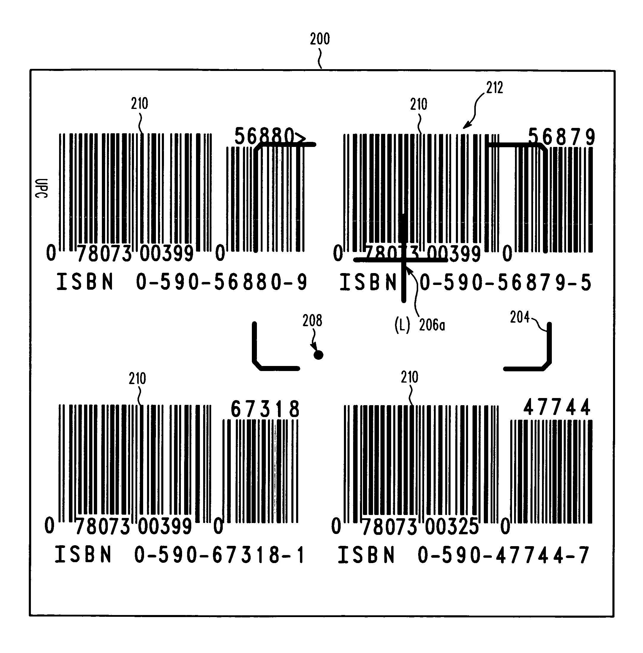
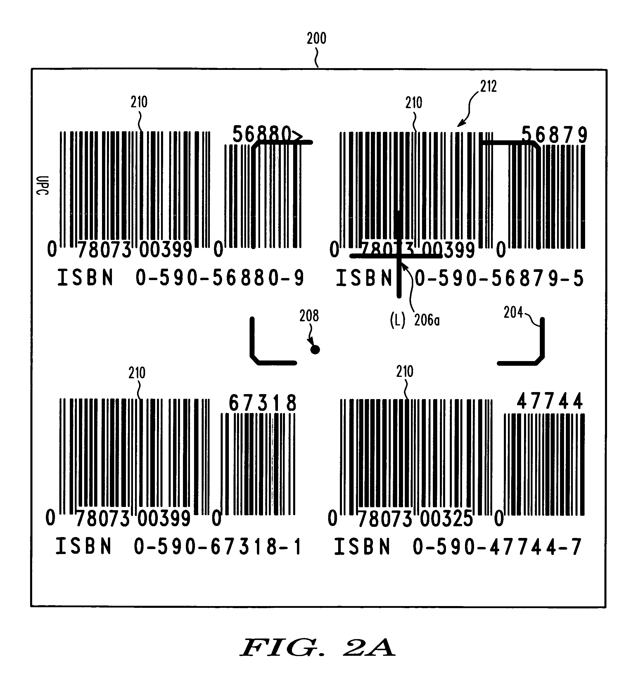
[0012]In accordance with this feature, a controller is operative for controlling the intensity of the laser beam during the aiming mode by increasing the intensity of the laser beam during the exposure time period to enhance detection and capture of the aiming pattern by the imager, and by decreasing the intensity of the laser beam outside the exposure time period. As discussed above, there are situations, such as in well-lit indoor environments or outdoors in sunlight, when a low contrast between the aiming pattern and the rest of the captured image results in the aiming pattern not being readily detected by the imager module. In some applications, the aiming pattern is washed out by the brighter ambient light. If the imager module cannot detect the aiming pattern, then the reader cannot select a desired optical code from among multiple codes that may be present in the field of view, for example, in the case of a shipping label that has multiple codes in the field of view, thereby resulting in the desired optical code not being read. Hence, by increasing the intensity of the laser beam, the brightness of the aiming pattern will increase, while the brightness of the rest of the image will remain the same and, as a result, the detection and capture of the aiming pattern by the imager are enhanced.
[0014]Hence, this invention proposes increasing the intensity of the laser beam only during a brief exposure time period during the aiming mode, and by decreasing the intensity of the laser beam outside the exposure time period. The exposure time period is a minor fraction of time compared to the duration of the aiming mode. The aiming laser is pulsed or energized only during the exposure time period. Decreasing the duration of the exposure time period will decrease the brightness of both the aiming pattern and that of the rest of the image by approximately the same factor. However, by simultaneously increasing the intensity of the laser beam and by decreasing the duration of the exposure time period, the brightness of the rest of the image will decrease more than that of the aiming pattern and, therefore, the contrast of the aiming pattern in the acquired image will improve, resulting in better detection of the aiming pattern. At the same time, the average intensity of the laser beam during the aiming mode is sufficient to render the aiming pattern visible to the user.
[0015]In accordance with another feature, the aiming controller controls the aiming laser to generate the laser beam as a plurality of pulses each having a high output power level or peak for brief pulse time durations less than the duration of the aiming mode, and having a low output power level during the remainder of the aiming mode, The fewer the number of peaks, and the shorter the time duration of each pulse, the higher the peak output power of each pulse can be. For example, for a class 2 laser with a 250 ms base time, detection of the aiming pattern will be enhanced by choosing each pulse with a pulse duration of 1 ms with a peak output power of 4 mW followed by an output power of 0.98 mW during the remaining 249 ms. Therefore, the detection of the aiming pattern in the acquired image, compared to the safety level of a constant output power of 1 mW, will increase by four times without decreasing the visibility of the aiming pattern to the user's eyes and without exceeding the laser safety limits.
[0017]In accordance with another feature of this invention, the method of reading an optical code during a reading mode is performed by generating an aiming pattern from a laser beam having a variable intensity during an aiming mode prior to the reading mode, detecting and capturing an image of the aiming pattern and the code over a field of view by exposure of an imager over an exposure time period during the aiming mode, detecting and capturing an image of the code over the field of view during the reading mode, and controlling the intensity of the laser beam during the aiming mode by increasing the intensity of the laser beam during the exposure time period to enhance detection and capture of the aiming pattern by the imager, and by decreasing the intensity of the laser beam frame outside the exposure time period for user safety.

Problems solved by technology

As discussed above, there are situations, such as in well-lit indoor environments or outdoors in sunlight, when a low contrast between the aiming pattern and the rest of the captured image results in the aiming pattern not being readily detected by the imager module.
If the imager module cannot detect the aiming pattern, then the reader cannot select a desired optical code from among multiple codes that may be present in the field of view, for example, in the case of a shipping label that has multiple codes in the field of view, thereby resulting in the desired optical code not being read.
However, the intensity of the laser beam cannot be increased too much and / or for too long without violating human eye exposure laser safety limits.
The laser typically has a generally constant output power safety level, which is limited and regulated depending on the class of the laser.
Output powers greater than those prescribed over longer than the prescribed time intervals are considered to be dangerous to the eyes of the user and bystanders.

Method used


Image

  • Imaging reader and method with enhanced aiming pattern detection
  • Imaging reader and method with enhanced aiming pattern detection
  • Imaging reader and method with enhanced aiming pattern detection

Examples


Embodiment Construction

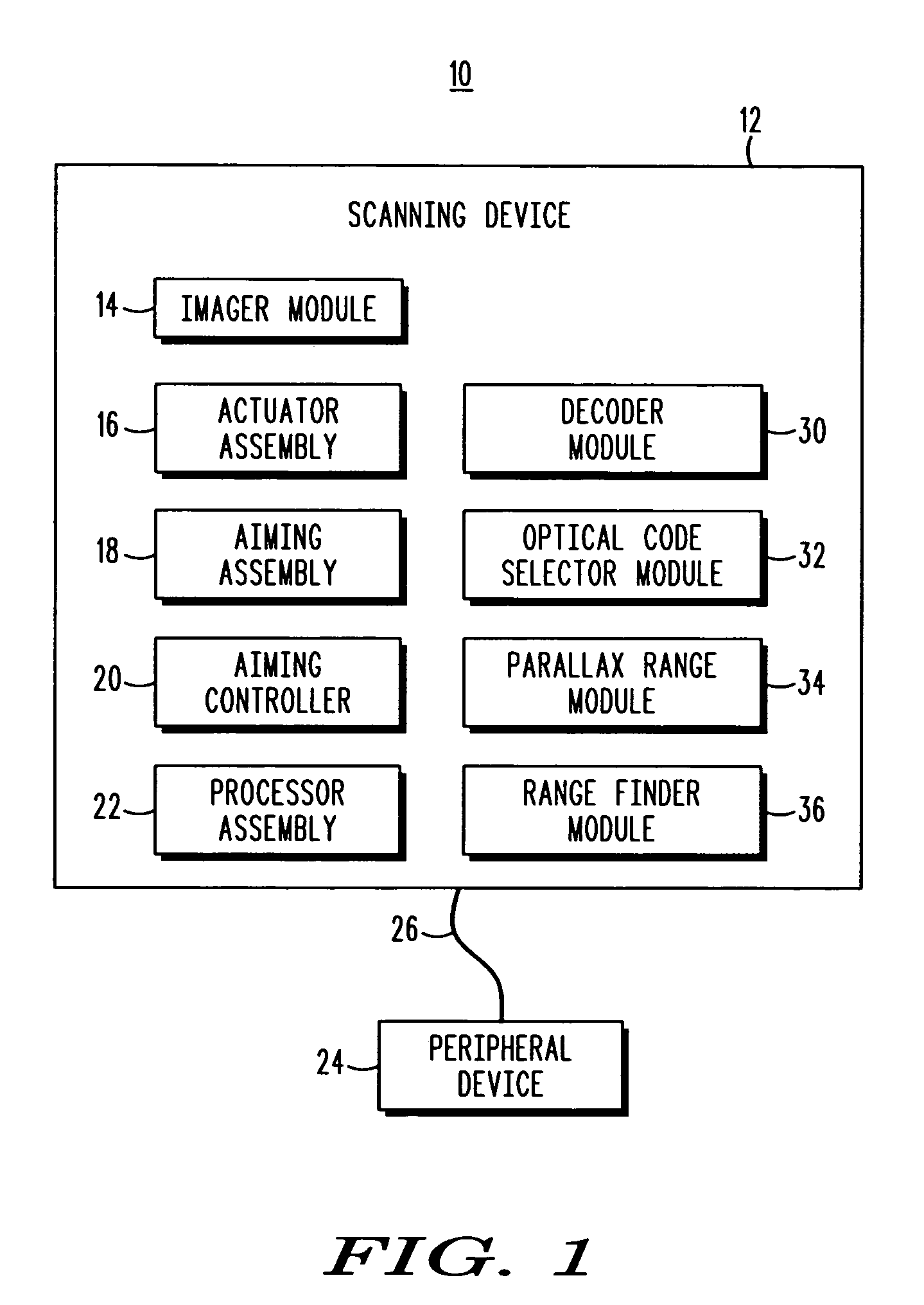
[0025]In FIG. 1, an optical code scanner system 10 for reading an optical code during a reading mode is shown, where the system 10 includes an imaging reader or scanning device 12 for reading an optical code, which may be, for example, a bar code symbol, a UPC / EAN symbol, a one-dimensional or multi-dimensional symbol, a textual code, etc. A “read” or “read operation” refers to imaging and decoding the optical code, but may further be understood as imaging and processing the optical code, such as for performing character recognition on the imaged optical code, transmitting or further processing the imaged optical code.

[0026]The scanning device 12 includes an imager module 14, an actuator assembly 16, an aiming assembly 18, an aiming controller 20, and a processor assembly 22. The scanning device 12 may be in communication with one or more peripheral devices 24, such as a keyboard, a display, a printer, a data storage medium, e.g., including storage for application software and / or dat...


PUM


Abstract

An image capture system for, and a method of, reading an optical code during a reading mode, comprise an aiming assembly including a laser for emitting a laser beam having a variable intensity, and for generating an aiming pattern from the laser beam during an aiming mode prior to the reading mode, and an imager for detecting and capturing an image of the aiming pattern and the code over a field of view by exposure over an exposure time period during the aiming mode, and for detecting and capturing an image of the code over the field of view during the reading mode. A controller is operative for controlling the intensity of the laser beam during the aiming mode by increasing the intensity of the laser beam during the exposure time period to enhance detection and capture of the aiming pattern by the imager, and by decreasing the intensity of the laser beam frame outside the exposure time period for user safety.

Description

BACKGROUND OF THE INVENTION[0001]This invention generally relates to an imaging reader for, and a method of, reading an optical code by visually positioning a laser-based aiming pattern relative to the code to be read during an aiming mode of operation and, more particularly, relates to enhancing detection of the aiming pattern during the aiming mode without violating human eye exposure laser safety limit standards and without reducing visibility of the aiming pattern to a user, especially in the presence of bright ambient light.[0002]Imaging readers have been developed heretofore for reading optical codes, such as one- or two-dimensional bar code symbols, appearing on a label or on a surface of an article. The symbol itself is a coded pattern of graphic indicia comprised of, for example, a series of bars of various widths spaced apart from one another to bound spaces of various widths, where the bars and spaces have different light reflecting characteristics. The imaging readers el...

Claims


Application Information

Patent Timeline
Patent Type & Authority Patents(United States)
IPC IPC(8): G06K7/14G03B7/08G06K9/24G06K7/10
CPCG06K2207/1018G06K2207/1011G06K7/14G06K7/10722
Inventor TRAJKOVIC, MIROSLAVGUREVICH, VLADIMIRZHANG, HENG
Owner SYMBOL TECH LLC
Learn More