AI technical title is built by Patsnap AI team. It summarizes the technical point description of the patent document.
a technology of rotary guide bearings and bearings, which is applied in the direction of mechanical equipment, couplings, transportation and packaging, etc., can solve the problems of limiting the application of environments, catastrophic system failure, and the radial stiffness of the beam arrangement is not radially symmetrical
Active Publication Date: 2014-12-02
VALOIS MICHAEL
View PDF24 Cites 6 Cited by
Summary
Abstract
Description
Claims
Application Information
AI Technical Summary
This helps you quickly interpret patents by identifying the three key elements:
Problems solved by technology
Method used
Benefits of technology
Benefits of technology
[0012]3) The proposed rotary flexure bearing is a seamless monolithic structure. The axial cross-section of the proposed rotary flexure bearing remains constant along the entire length permitting use of the wire EDM process for fabrication of this rotary flexure bearing from any metal. This constant axial cross-section also simplifies the design of a mold for making the proposed rotary flexure bearing from non-metallic materials such as plastic.
[0013]4) The radially symmetrical design of the proposed rotary flexure bearing yields a radially symmetrical stiffness.
Problems solved by technology
Motivation for the proposed rotary flexure bearing is partially based on the limited availability of high quality rotary flexure bearings.
This choice of material and fabrication technique favors mass production but limits application to environments benign enough for 400 series stainless steel and the brazing material.
Failure of any brazed joint could cause catastrophic system failure.4) In addition to a constantly shifting axis of rotation and multiple single point failure sites, the radial stiffness of this beam arrangement is not radially symmetrical.
Method used
Image
Click on the blue label to locate the original text in one second.
Reading with bidirectional positioning of images and text.
Examples
Embodiment Construction
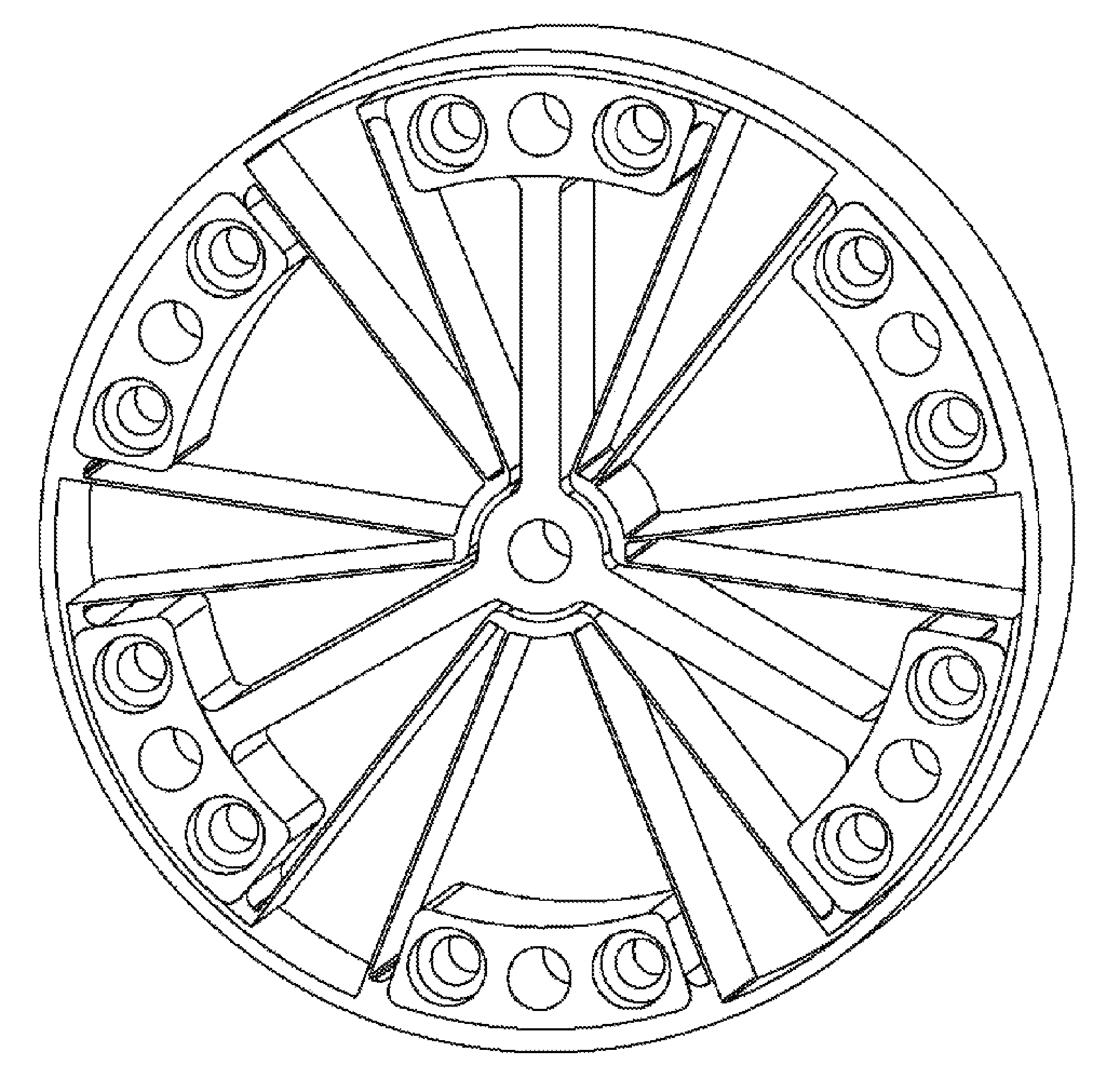
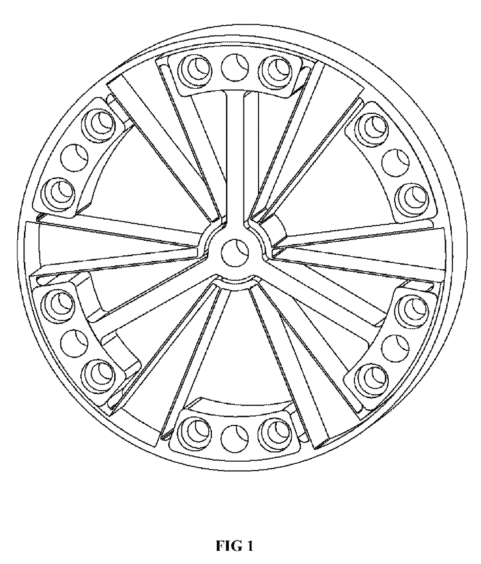
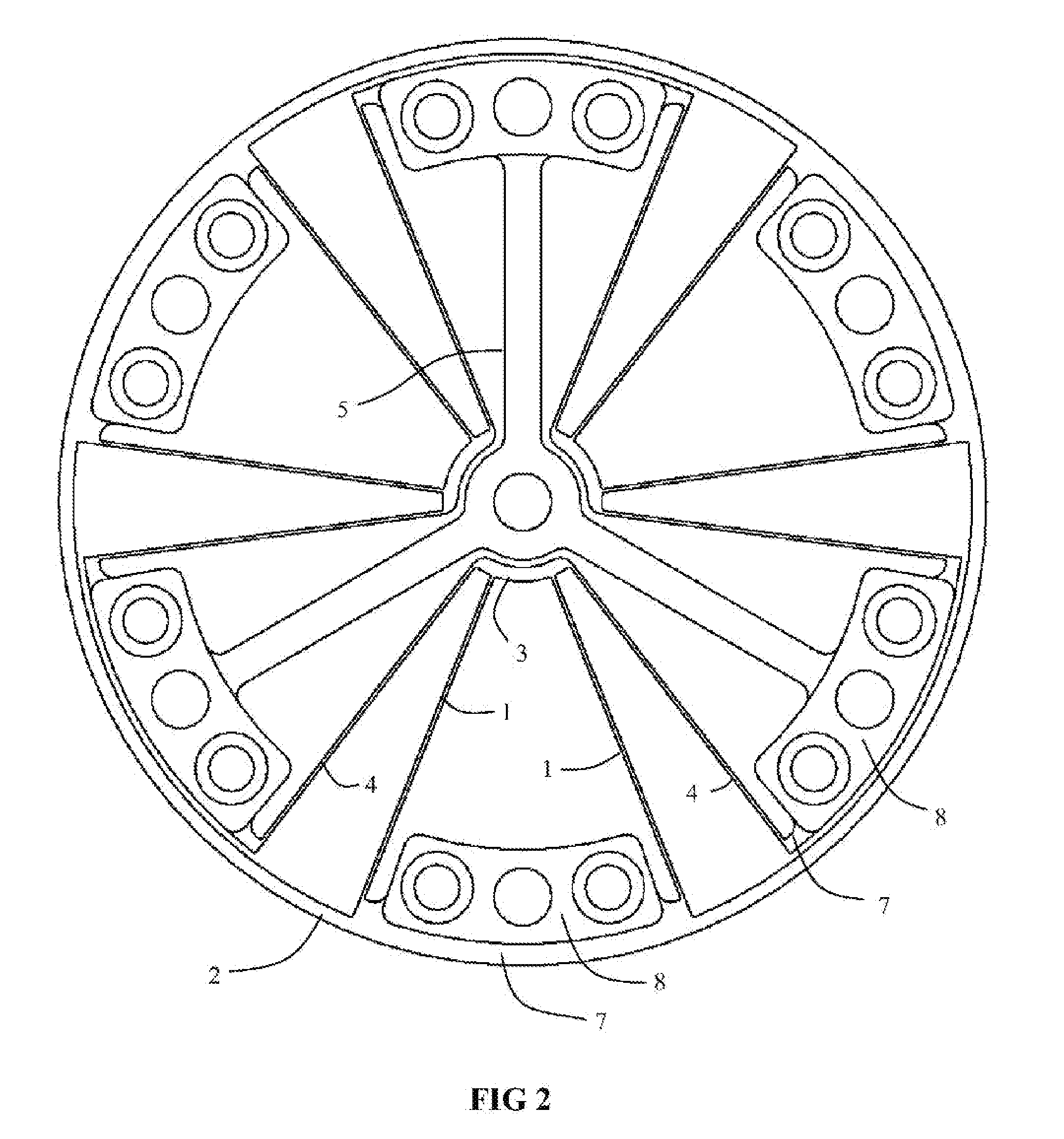
[0018]A compound flexure stage is the basis of the proposed rotary flexure bearing. To help illustrate the operating principle and design of this compound flexure stage, a rotary flexure bearing with three compound flexure stages is described herein. Each compound flexure has exactly four blade flexures. All twelve blade flexures are the same thickness, width, length, and made of the same material, therefore have the same stiffness. The two inner blade flexures 1 in each compound stage connect the outer hub 2 of the rotary flexure bearing to an intermediate link 3. The two outer blade flexures 4 in each compound stage connect the inner hub 5 to the intermediate link 3. Each of the three compound stages is defined by one inner blade flexure stage, having exactly two blade flexures, and one outer blade flexure stage, having exactly two blade flexures. The inner blade flexure stage consists of the inner blade flexures 1 and the intermediate link 3 while the outer blade flexure stage co...
PUM
Abstract
This rotary flexure bearing consists of concentric inner and outer hubs connected by compound flexure stages. These compound flexure stages provide the angular compliance required for bearing rotation as well as compliance for flexure foreshortening while holding a constant axis of rotation over the entire range of motion. This design offers large angular displacement, low operating stress, low operating torque, and high stiffness in the five noncompliant degrees of freedom. The rotary flexure bearing described herein has applications in precision mechanics, particularly opto-mechanics. Specific applications include but are not limited to wafer and reticle alignment stages used in microlithography systems, mirror pointing and scanning mechanisms used in tactical and spaceborne systems, as well as flip-in mechanisms used in multiple field of view optical systems.
Description
U.S. PATENT DOCUMENTS[0001]U.S. PATENT DOCUMENTS2,291,6128 / 1942Draper73 / 504.092,690,0149 / 1954Draper33 / 3222,735,7312 / 1956Freebairn74 / 5.42,931,0924 / 1960Humphrey403 / 2913,073,5841 / 1963Troeger464 / 1003,807,0294 / 1974Troeger29 / 4163,813,0895 / 1974Troeger267 / 1603,825,9927 / 1974Troeger29 / 4364,802,7842 / 1989Brooks403 / 2914,812,0723 / 1989Brooks403 / 2915,620,1694 / 1997Payne267 / 1606,146,04411 / 2000Calvet403 / 119BACKGROUND OF THE INVENTION[0002]This invention generally relates to a flexure based rotary guide bearing. Flexures have been used successfully in simple and inexpensive as well as complicated and expensive motion systems for centuries. Since they operate by bending, not rolling or sliding, flexures have the inherent advantage of friction-free motion. This key feature allows engineers to build positioning systems with nearly unlimited precision and accuracy. They are also easy to design and fabricate. However, even with these desirable attributes there are few flexure based bearings available commer...
Claims
Application Information
Patent Timeline
Application Date:The date an application was filed.
Publication Date:The date a patent or application was officially published.
First Publication Date:The earliest publication date of a patent with the same application number.
Issue Date:Publication date of the patent grant document.
PCT Entry Date:The Entry date of PCT National Phase.
Estimated Expiry Date:The statutory expiry date of a patent right according to the Patent Law, and it is the longest term of protection that the patent right can achieve without the termination of the patent right due to other reasons(Term extension factor has been taken into account ).
Invalid Date:Actual expiry date is based on effective date or publication date of legal transaction data of invalid patent.

