Structure of a scanning window

a scanning window and structure technology, applied in the field of scanning windows, can solve the problems of affecting the ability of the support to position the glass, the structural strength of the top surface, etc., and achieve the effect of reducing the size of the housing, and simplifying the design of the mold for forming the housing

Inactive Publication Date: 2009-12-08
AVISION
View PDF5 Cites 0 Cited by
  • Summary
  • Abstract
  • Description
  • Claims
  • Application Information

AI Technical Summary

Benefits of technology

[0010]One embodiment of the prior art has shortcomings such as complicated bottom structure of the housing, difficulty in the design of cooling water paths for molds, and long cooling cycles. Another embodiment of the prior art may weaken the structural strength of the top surface and, thus, affect the capability of the support to positioning the glass. The present invention provides an innovative structure which has a simpler mold design and smaller in dimension than the prior art embodiments and makes it easier in the assembly of the scanning window with better positioning.
[0012]The base is used as a connection for the upper and lower housings of the housing when the upper and lower housings are assembled. The base is formed at the cut-off end of the strengthening structure on the inner wall of the housing. The design of the mold for forming the housing is also simplified with this structure. The combination of the base and the supporting block is capable of supporting the glass more rigidly and providing a more effective positioning for the glass. Moreover, the base and the supporting block are disposed away from the lower housing and do not collide with the carriage module. The size of the housing is, thus, reduced.

Problems solved by technology

Another embodiment of the prior art may weaken the structural strength of the top surface and, thus, affect the capability of the support to positioning the glass.

Method used


Image

  • Structure of a scanning window
  • Structure of a scanning window
  • Structure of a scanning window

Examples


Embodiment Construction

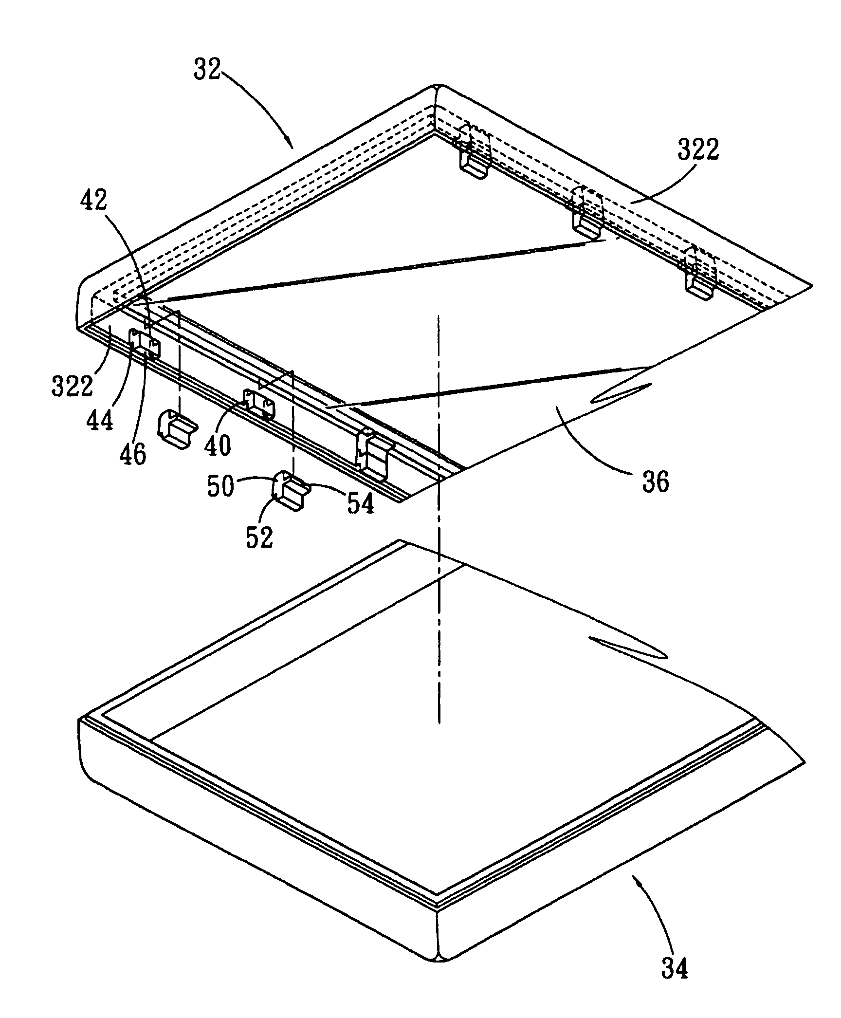
[0018]As shown in FIG. 3, an image scanning device comprises an upper housing 32 and a lower housing 34. The lower housing 34 is formed as a container for a carriage module (not shown in the figure) which moves in reciprocating motion. The upper housing 32 is formed as a frame with an opening 326 in the middle. A glass (transparent platen) 36 is disposed adjacent to the opening 326 in the upper housing 32. The housing of the image scanning device is formed when the upper housing 32 and the lower housing 34 hasp with each other.

[0019]A plurality of bases 40 is disposed on the inner side of the vertical part 322 of the upper housing 32. One end of the base 40 is formed to be an engagement part 42 that has a stepped structure and is positioned corresponding to the top portion 324 of the upper housing 32. Another end of the base 40 is formed to be another engagement part 44 with a stepped structure and an opening 46 is formed on one side thereof.

[0020]The upper housing 32 has a strength...


PUM


Abstract

A structure of a scanning window of an image scanning device has a housing, a transparent platen, a plurality of bases and a plurality of supporting blocks. The bases are formed on the inner walls of the housing. The supporting blocks are disposed on the bases and each supporting block has a supporting part. The transparent platen is disposed between the top portion of the housing and the supporting parts. Thus, the transparent platen is fixed in place by the supporting parts and the top portion of the image scanning device.

Description

BACKGROUND OF THE INVENTION[0001]1. Field of the Invention[0002]The present invention relates generally to a scanning window, and more particularly to an assembly structure for a glass disposing on the top of an image scanning device. A sheet is put on the glass and scanned by a carriage module. The image scanning device could be a flatbed scanner or a sheet-fed scanner. The structure is used to support the glass so that it can be fixed in the housing of the image scanning device.[0003]2. Description of the Prior Art[0004]An image scanning device of prior art includes a housing, a glass, and a carriage module. Since the glass is disposed in the housing and adjacent to the top thereof, an appropriate support is required for the positioning of the glass. A carriage module is disposed in the housing and capable of reciprocating motion to acquire images of a sheet to be scanned and perform image processing operations.[0005]As FIG. 1 shows, the image scanning device has a plurality of mo...

Claims


Application Information

Patent Timeline
Patent Type & Authority Patents(United States)
IPC IPC(8): H04N1/04G03G15/20H04N1/10
CPCH04N1/1065H04N1/10
Inventor CHANG, YUINGCHENG, SUNG-PO
Owner AVISION
Why Eureka
Try Eureka