Method for forming thin-wall metal component by controlling inflation position

A metal component and thin-walled technology, which is applied in the field of forming thin-walled metal components by controlling the inflated position, can solve problems such as uneven distribution of wall thickness, weakening of component performance, cracking, etc., so as to solve the uneven distribution of wall thickness and improve the distribution of wall thickness Uniformity, the effect of simplifying the process flow

Pending Publication Date: 2022-07-08
DALIAN UNIV OF TECH
View PDF7 Cites 0 Cited by
  • Summary
  • Abstract
  • Description
  • Claims
  • Application Information

AI Technical Summary

Problems solved by technology

[0006] The purpose of the present invention is to provide a method for forming thin-walled metal components by controlling the inflated position, which can solve the problem that the position of the inflated port is fixed in the existing high-temperature pneumatic bulging process, and the inflated position cannot be changed. The temperature field distribution is u

Method used


Image

  • Method for forming thin-wall metal component by controlling inflation position
  • Method for forming thin-wall metal component by controlling inflation position
  • Method for forming thin-wall metal component by controlling inflation position

Examples


Embodiment 1

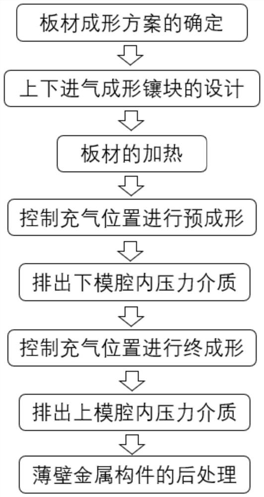
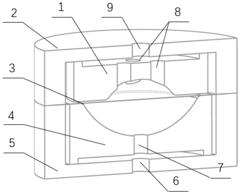
[0028] Example 1: Combination figure 1 , figure 2 , Figure 3, Figure 4 illustrates, a method for controlling the inflation position to form a thin-walled metal member proposed by the present invention, the method is carried out according to the following steps:

[0029] Step 1. Determination of sheet forming scheme: Analyze the shape characteristics of thin-walled metal components, determine the material of the slab, use wire cutting to cut out the appropriate sheet size, and determine the sheet forming scheme through theoretical calculation or finite element simulation analysis.

[0030] Step 2. Design of the upper and lower air intake forming inserts: According to the characteristic size of the thin-walled metal components, design the corresponding characteristic contours of the upper and lower forming inserts, and analyze the thin-walled metal components that are prone to wall thickness reduction and thinning during the forming process. For the location of material accumu...

Embodiment 2

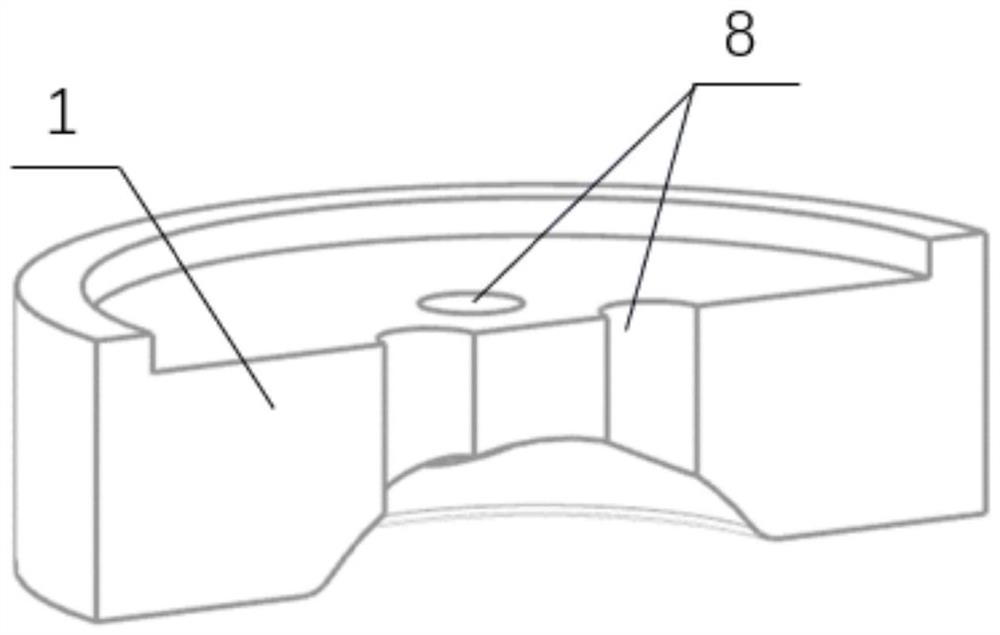
[0038] Embodiment 2: Referring to Fig. 3, in step 2, upper and lower air intake forming inserts of different shapes and sizes can be designed according to the forming needs. If a forming part with many local features is formed, it is necessary to design multiple shapes for the upper and lower inserts If the formed part has multiple large curvature features and the material flow behavior is complex, it is necessary to reasonably use finite element simulation software for calculation to analyze the material flow characteristics in the pre-forming and final forming process, and combine the calculation results for the upper air forming process. The pre-formed contour design is performed on the insert to make it pre-formed into a rough outline shape, and then the final forming contour design is performed on the lower air intake forming insert. The pre-forming and final forming effects are coupled to form an ideal forming with large curvature characteristics. It solves the problem th...

Embodiment 3

[0040] Embodiment 3: Referring to Fig. 3, in step 2, according to the shape characteristics of the thin-walled metal components, the corresponding air inlets are designed at different positions of the upper and lower air intake forming inserts. For example, when forming deep cavity thin-walled parts, the bottom If the wall thickness of the fillet area is thin, when designing the air inlet of the lower air intake forming insert, it is necessary to take into account the reasonable regulation of the material flow in the bottom fillet area during pre-forming, and use the flow characteristics of the material during inflation to reduce the thickness of the material in advance. Gather material in the area, that is, design the corresponding inflatable port at the corresponding position of the rounded area, gather the material during pre-forming, and then design the corresponding inflatable port on the upper air intake forming insert according to the wall thickness distribution character...


PUM


Abstract

The invention belongs to the technical field of thin-wall metal component forming and manufacturing, and relates to a method for forming a thin-wall metal component by controlling an inflation position, which can solve the problems that the position of an inflation inlet is fixed, the inflation position cannot be changed, and the temperature field distribution of a plate is unreasonable due to inflation of high-pressure gas in the existing high-temperature air pressure bulging process. The defects of local thinning, cracking, uneven wall thickness distribution and the like occur in the forming process, and for thin-wall metal components with complex structures, flowing of materials cannot be reasonably regulated and controlled in the forming process, the materials cannot be evenly distributed, and the performance of the components is weakened are solved. According to the method, the inflation position is flexibly designed according to the structural characteristics of the complex thin-wall metal component, the purpose of regulating and controlling reasonable distribution of the plate temperature field is achieved, then the plastic deformation degree of different areas of the plate is regulated and controlled, and the problems of serious wall thickness reduction and serious material accumulation during local feature forming are solved; a complex thin-wall metal component can be subjected to multiple times of bulging, flowing of materials is reasonably regulated and controlled, material distribution is adjustable and controllable, and the performance of a bulging part is improved.

Description

technical field [0001] The invention belongs to the technical field of forming and manufacturing thin-walled metal components, and in particular relates to a method for forming thin-walled metal components by controlling the inflation position. Background technique [0002] With the development of the automotive industry and the aerospace industry, the application of thin-walled metal structural parts is becoming more and more extensive. This type of parts usually requires high precision, high performance and high reliability, which directly affects the service performance of the equipment. They are the key components of new energy vehicles and new generation airborne equipment. Such thin-walled metal components are often made of lightweight and high-performance materials such as aluminum alloys, magnesium alloys, and titanium alloys. Such materials have low plasticity and poor formability at room temperature, so they need to be formed at high temperatures, and their shape,...

Claims


Application Information

Patent Timeline
IPC IPC(8): B21D26/021B21D26/031
CPCB21D26/021B21D26/031
Inventor 何祝斌赵聪
Owner DALIAN UNIV OF TECH
Why Eureka
Try Eureka