Safety and clamping device for an apparatus for fabricating parts

a safety and clamping device technology, applied in the field of molding machines, can solve the problems of affecting the safety of the clamping device, etc., and achieves the effects of eliminating accidents and injuries in the working environment, saving manufacturing time, and simple production, installation and servi

Inactive Publication Date: 2014-12-02
AB SKF
View PDF3 Cites 3 Cited by
  • Summary
  • Abstract
  • Description
  • Claims
  • Application Information

AI Technical Summary

Benefits of technology

[0013]An advantage of the present invention is to provide the improved apparatus and method for quick release of the molds and replacement of the molds thereby saving time during manufacturing of the parts of different configurations wherein the molds can be replaced within several minutes as compared to some prior art mold devices wherein it may take up to several hours in order to replace the molds.
[0014]Another advantage of the present invention is to provide the improved molding apparatus and method for securing the first or upper mold plate of the injection molding machine against inadvertent closing of the two molds relative to one another or dropping of the first mold in case of power outage or other mechanical or electrical malfunctions of the apparatus.
[0015]Still another advantage of the present invention is to provide the improved apparatus and method for holding a mold assembly including first and second mold portions that is simple in production, installation, and service and can serve several purposes such as clamping of the upper mold to the housing and secure the upper mold in place in case of power lose and any external or internal impacts on the housing to prevent shutting or inadvertent drop of the upper mold against the bottom mold to eliminate any accident and injuries in a working environment during production process.
[0016]Still another advantage of the present invention is to provide the improved apparatus and method for securing the upper mold of the injection molding machine by simple means, which obviates prior art shortcomings by preventing an inadvertent closing of the upper mold and to thereby realize improved security of operation as well as retaining good accessibility between the two mold mounting plates.
[0017]Still another advantage of the present invention is to provide the improved apparatus for forming parts that is compact in design and can be utilized in various industrial applications.

Problems solved by technology

This type safety device requires relatively high expenditures with respect to mechanics and maintenance and in addition, the device itself also impedes accessibility to the space between the two mold mounting plates.
The device taught by the U.S. Pat. No. 7,179,074 to Zellerohr et al., is very complex and bulky and does not provide an alternative design that is compact and can serve several purposes such as clamping the upper mold to the housing and secure the upper mold in place in case of power outage and any external or internal impacts on the housing where the mold halves are positioned that may cause shutting or inadvertent drop of the upper mold against the bottom mold.
Similar to the device taught by the U.S. Pat. No. 7,179,074 to Zellerohr et al., the molding machine taught by the U.S. Pat. No. 4,029,457 to Yamamoto is very complex and bulky and does not provide an alternative design that is compact and can serve several purposes such as clamping the upper mold to the housing and secure the upper mold in place in case of power outage and any external or internal impacts on the housing where the mold halves are positioned that may cause shutting or inadvertent drop of the upper mold against the bottom mold.
The mold clamping apparatus taught by the U.S. Pat. No. 6,533,573 to Tamaki et al., for example, is very complex and bulky and does not provide an alternative design that is compact and can serve several purposes such as clamping the upper mold to the housing and secure the upper mold in place in case of power outage and any external or internal impacts on the housing where the mold halves are positioned that may cause shutting or inadvertent drop of the upper mold against the bottom mold.

Method used


Image

  • Safety and clamping device for an apparatus for fabricating parts
  • Safety and clamping device for an apparatus for fabricating parts
  • Safety and clamping device for an apparatus for fabricating parts

Examples


Embodiment Construction

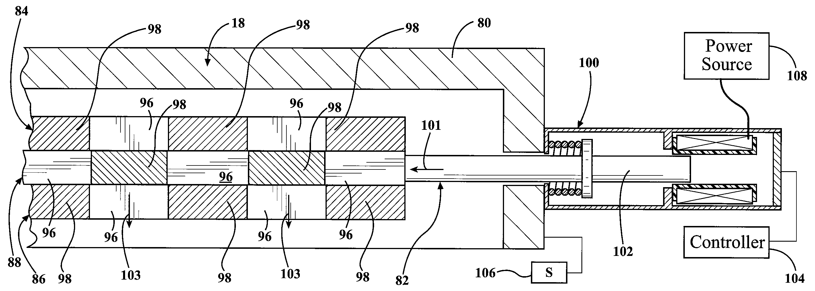
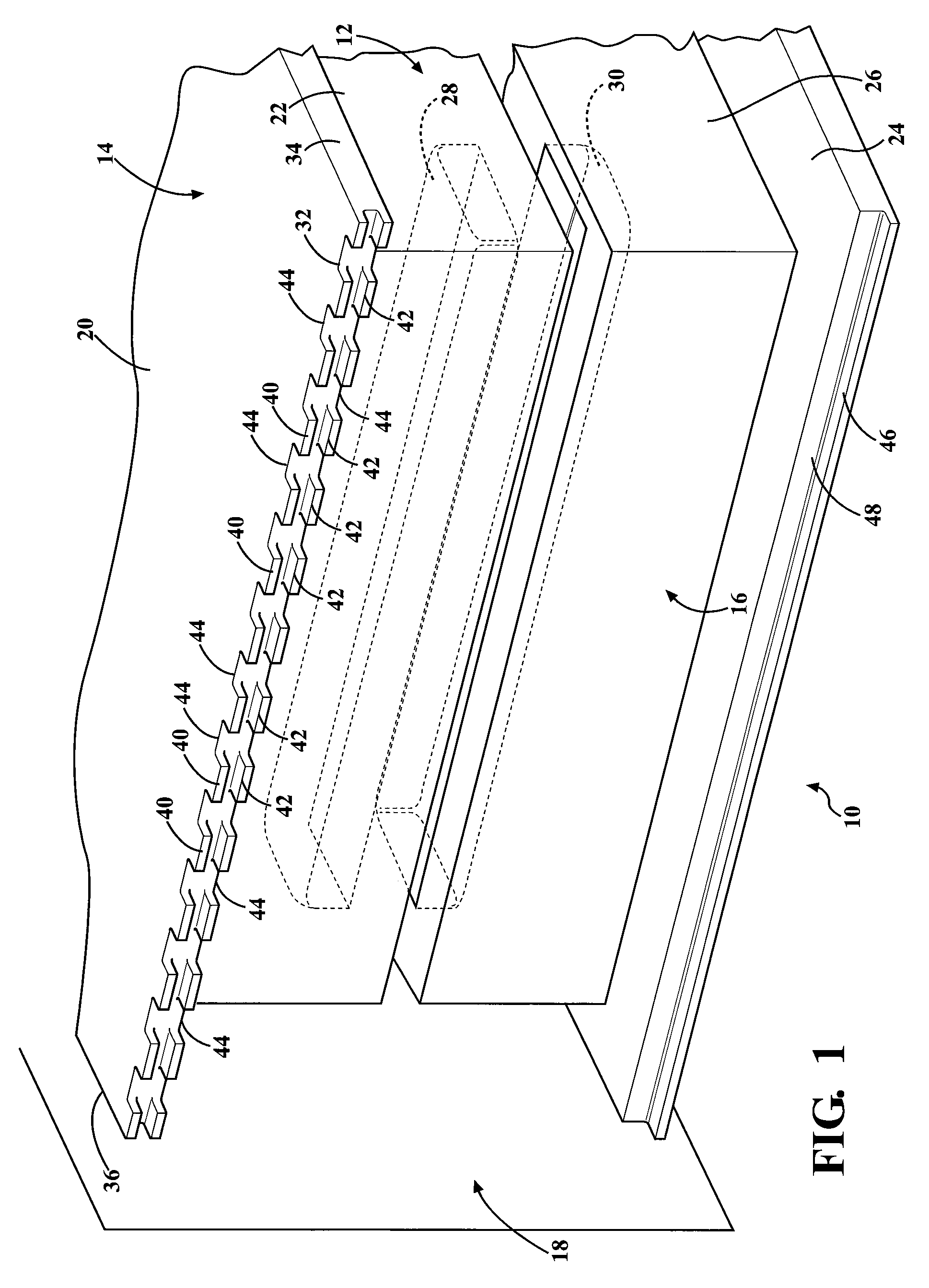
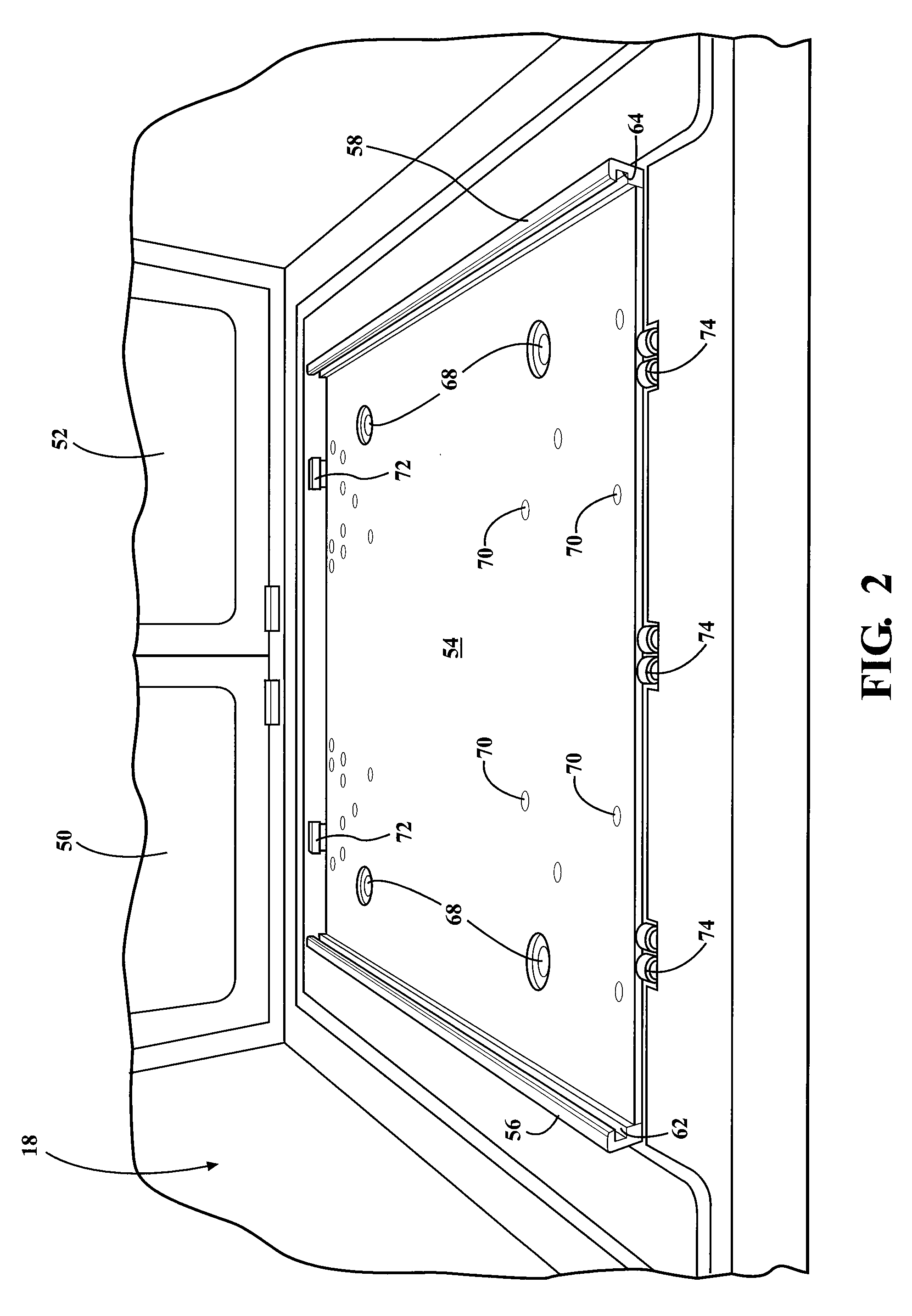
[0025]Referring to FIGS. 1 through 7, wherein like numerals indicate like or corresponding parts throughout the several views, a molding apparatus (the apparatus), generally shown at 10 in FIGS. 1 and 3 through 7, is used for fabricating parts made from rubber, plastics, metal and metal alloys. The apparatus 10 receives a mold device, generally indicated at 12 that includes a first mold part or half, generally indicated at 14 and a second mold part or half, generally indicated at 16, operably connected with one another to define a cavity therebetween to receive at least one of polymeric, non-polymeric materials for forming parts. Alternatively, the apparatus 10 is also configured to perform stamping operations wherein blanks of at least one of metallic and organic materials (not shown) are placed between the first mold part 14 and the second mold part 16 thereby stamping parts (not shown). The apparatus 10 may also be used for compression and transfer molding operations as well with...


PUM

PropertyMeasurementUnit
power lossaaaaaaaaaa
poweraaaaaaaaaa
displacementaaaaaaaaaa

Abstract

An apparatus of the present invention presents a housing for engaging a mold device that includes a top plate having a top mold and a bottom plate having a bottom mold. The top plate presents side edges presenting a plurality of male elements extending therefrom. A top portion of the housing presents a safety and locking device (the device) to secure the top plate. The device presents several plates movable relative one another to secure the top plate. In case of a power outage, an actuator cooperably connected with the device prevents a shaft, connected to one of the plates, to move back to its idle position thereby locking the top plate within the device to prevent disengagement of the top plate from the device.

Description

FIELD OF THE INVENTION[0001]The present invention relates to molding machines, particularly to a safety unit installed in the molding machine.BACKGROUND OF THE INVENTION[0002]Injection molding is a manufacturing process for producing parts from both thermoplastic and thermosetting plastic materials. Injection molding machines include at least two mold mounting plates, with one mold mounting plate fixedly anchored upon a machine bed and with the other mold mounting plate movable relative thereto. The mold mounting plates carry respective half-molds, i.e. an upper mold and a bottom mold. Opening and closing of the cavity involves a displacement of the moving mold mounting plate or an upper mounting plate relative to the fixed mold mounting plate, i.e. a bottom mounting plate controlled by a mold closing unit. Material, such as thermoplastic or thermosetting plastic materials, is fed into a heated barrel, mixed, and forced into the mold cavity defined by the upper and bottom molds, whe...

Claims


Application Information

Patent Timeline
Patent Type & Authority Patents(United States)
IPC IPC(8): B29C37/00B29C45/64B29C33/30
CPCB29C45/641B29C2037/94B22D17/2092B29C45/84B29C33/30
Inventor NOTTER, DAVID A.
Owner AB SKF
Why Eureka
Try Eureka