Set-top box having microperforations

a technology of micro-perforation and set-top boxes, which is applied in the field of set-top boxes, can solve the problems of increasing the chance of liquid and insect entry into the set-top box, damage to the set-top box, etc., and achieves the effect of enhancing the heat removal featur

Active Publication Date: 2014-12-02
INTERDIGITAL CE PATENT HLDG
View PDF51 Cites 17 Cited by
  • Summary
  • Abstract
  • Description
  • Claims
  • Application Information

AI Technical Summary

Benefits of technology

[0006]An electronic device having features that remove heat and prevent liquid and insect entry comprises an outer casing having a top and a bottom in which the outer casing has heat venting perforations on any of its sides. The device further includes a bottom frame inside the outer casing in which the bottom frame has a heatsink surrounded by a peripheral area and the heatsink can be raised with respect to the peripheral area, wherein the peripheral area can have apertures. An interior electronic component or circuit board is over the bottom frame and a heatsinking element can be over the interior electronic component. The heatsinking element can have a central region in thermal contact with the heatsink and a peripheral portion in which the peripheral portion has louvers, wherein the central region can be depressed with respect to the peripheral portion and the interior electronic component or circuit board has a thermal contact region that permits the heatsink and central region to be in thermal contact. The louvers can be oriented in more than one direction and can be oriented to be directed toward the front, back, and sides of the device. The bottom frame can have two opposing sidewalls each having openings and clasps adjacent to the openings, wherein the openings are designed to accommodate engagement members of exterior end caps of the device. The engagement members engage the clasps through the openings which locks the end caps to the bottom frame and wherein the clasps can be narrower than the engagement members along a vertical dimension. The bottom frame can also have a rear wall having unlocking apertures adapted to permit unlocking prongs of a disengagement tool to enter therethrough and release the engagement members from the clasps, thereby permitting the ends caps to be unlocked from the bottom frame. The perforations of the casing can have opening dimensions in the range of 0.5 to 1 mm. Additionally, the heat removing features which include the heatsink, heatsink element, and perforations are designed to work without the need for a fan. The heat removing features can be enhanced by providing a base stand that permits the device stand vertically such that that the top and the bottom of the outer casing are oriented vertically.

Problems solved by technology

Particular problem that set-top boxes face are damage due to liquid entry, insect entry, and heat generation.
However, venting apertures, which are often used for heat dissipation, unfortunately increase the opportunity of liquid and insect entry.

Method used


Image

  • Set-top box having microperforations
  • Set-top box having microperforations
  • Set-top box having microperforations

Examples


Embodiment Construction

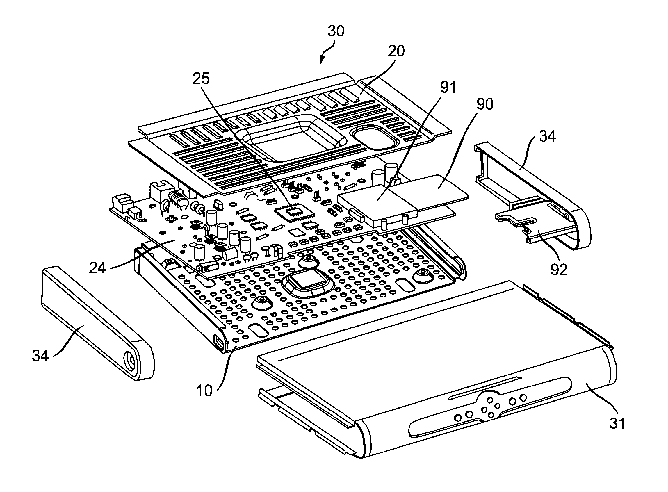
[0018]The set-top box 30 or the like according to the invention includes outer casing 31 having micro-perforations 36, an interior bottom frame 10 having a centrally located heatsink 11, a circuit board 24 or the like on the bottom frame 10, and a louvered heatsinking element 20 over the circuit board 24 and in thermal contact with the heatsink 11.

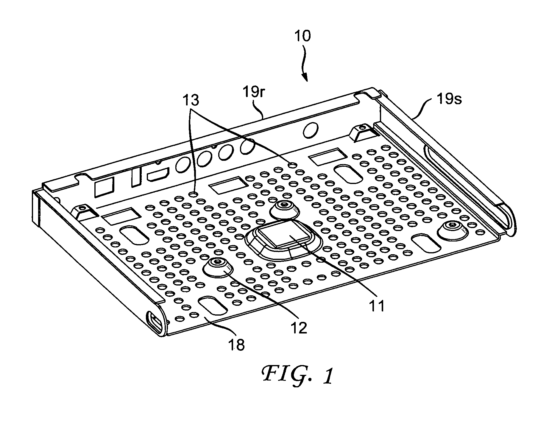
[0019]FIG. 1 shows the interior bottom frame 10 of the set-top box 30 having the centrally located heatsink 11. The heatsink 11 can be somewhat off center and is preferably raised from the base portion 18 of the frame 10. The frame 10 can also have upstanding sidewalls 19s, a rearwall 19r, spacers 12 for supporting internal components, and apertures 13 for improved heat flow and distribution.

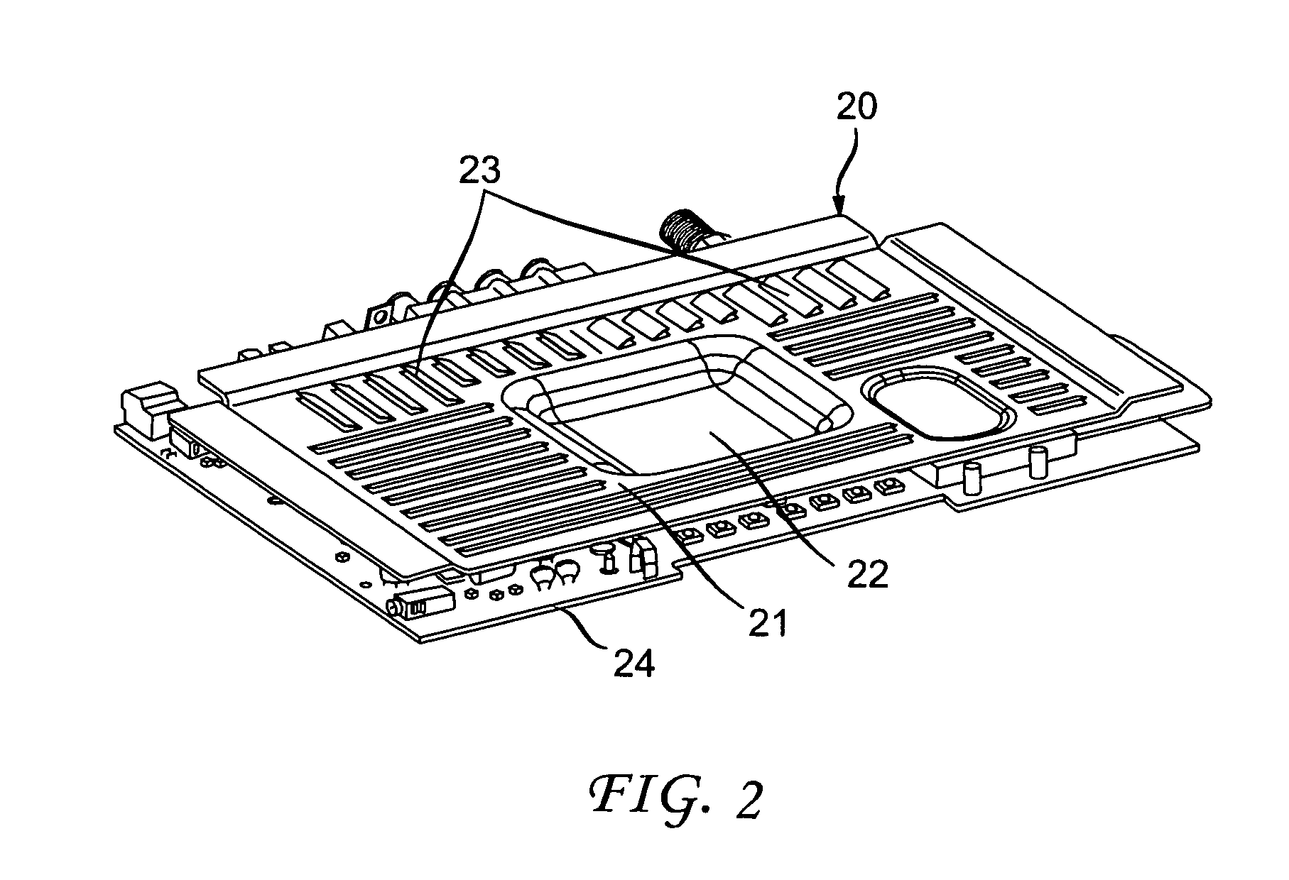
[0020]FIG. 2 shows a louvered heatsinking element 20 which is to be mounted parallel to the base portion 18 of the interior bottom frame 10 and preferably over the frame 10. FIG. 2 includes in the view the circuit board 24 which can be located between ...


PUM


Abstract

The set-top box includes an outer casing having micro-perforations, an interior bottom frame having a centrally located heatsink, a circuit board on the bottom frame and a louvered heatsinking element over the circuit board and in thermal contact with the heatsink.

Description

CROSS-REFERENCE TO RELATED APPLICATIONS[0001]This application claims the benefit, under 35 U.S.C. §365 of International Application PCT / US2010 / 003080, filed Dec. 2, 2010 which was published in accordance with PCT Article 21(2) on Jun. 16, 2011 in English and which claims the benefit of U.S. provisional patent application No. 61 / 283,815, filed Dec. 9, 2009.FIELD OF THE INVENTION[0002]The present invention relates to set-top boxes.BACKGROUND OF THE INVENTION[0003]Set-top boxes continue to be in high demand and an ever increasing need exists to reduce the size and improve aesthetic appeal, performance, and robustness of these devices and the like.[0004]Particular problem that set-top boxes face are damage due to liquid entry, insect entry, and heat generation. However, venting apertures, which are often used for heat dissipation, unfortunately increase the opportunity of liquid and insect entry. As such, a need exists to address each of these problems without creating or augmenting oth...

Claims


Application Information

Patent Timeline
Patent Type & Authority Patents(United States)
IPC IPC(8): H05K7/20
CPCH05K7/20445
Inventor RITTER, DARIN BRADLEYHUNT, MICKEY JAYGYSIN, MARK WILLIAM
Owner INTERDIGITAL CE PATENT HLDG
Why Eureka
Try Eureka