Sleeve for a punch assembly

a technology for assembly sleeves and punches, which is applied in the field of sleeves for punch assemblies, can solve the problems of high tool wear cost, less ideal punch/die clearance, and high frequency of “chipping” the punch or die cutting edge, and achieve the effects of reducing the elastic deflection of the draw stud, reducing the bending moment, and adding rigidity to the draw stud

Active Publication Date: 2014-12-09
GREENLEE TEXTRON
View PDF9 Cites 20 Cited by
  • Summary
  • Abstract
  • Description
  • Claims
  • Application Information

AI Technical Summary

Benefits of technology

[0010]A punch assembly includes a punch, a sleeve, a draw stud and a die. The sleeve adds rigidity to the draw stud, thereby reducing elastic deflection of the draw stud, reducing bending moment on the draw stud, reducing punching force, and extending the punch, draw stud and die fatigue life. The sleeve also aids in axial alignment of the punch, die and workpiece with a pilot hole drilled through a workpiece.

Problems solved by technology

A less ideal punch / die clearance leads to a higher frequency of “chipping” the punch or die cutting edge due to misalignment of the punch and die.
With regard to cutting a hole in 10 gage stainless steel, such a hole can be cut with great physical effort and high tool wear cost.
All these methods, however, are labor intensive and may wear out several tools in order to make just one hole.

Method used


Image

  • Sleeve for a punch assembly
  • Sleeve for a punch assembly
  • Sleeve for a punch assembly

Examples


Embodiment Construction

[0024]While the invention may be susceptible to embodiment in different forms, there is shown in the drawings, and herein will be described in detail, a specific embodiment with the understanding that the present disclosure is to be considered an exemplification of the principles of the invention, and is not intended to limit the invention to that as illustrated and described herein. Therefore, unless otherwise noted, features disclosed herein may be combined together to form additional combinations that were not otherwise shown for purposes of brevity.

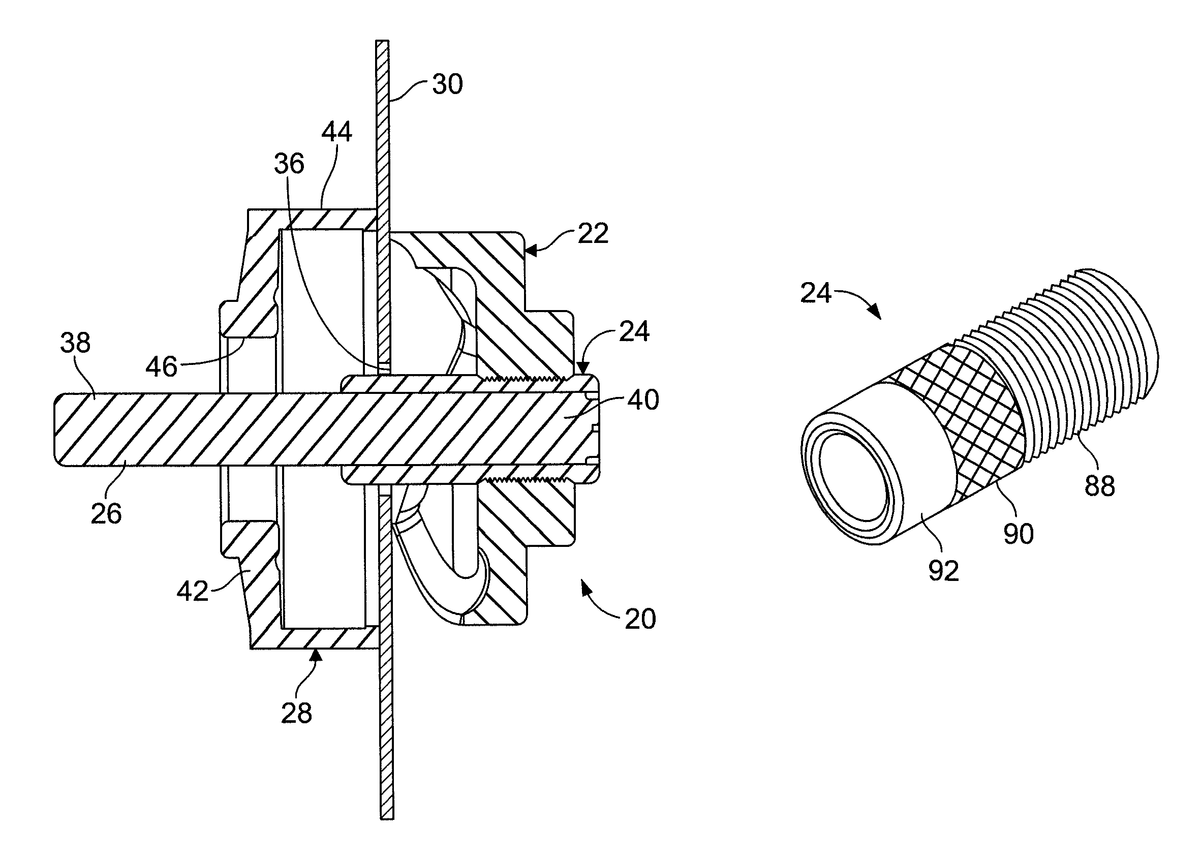
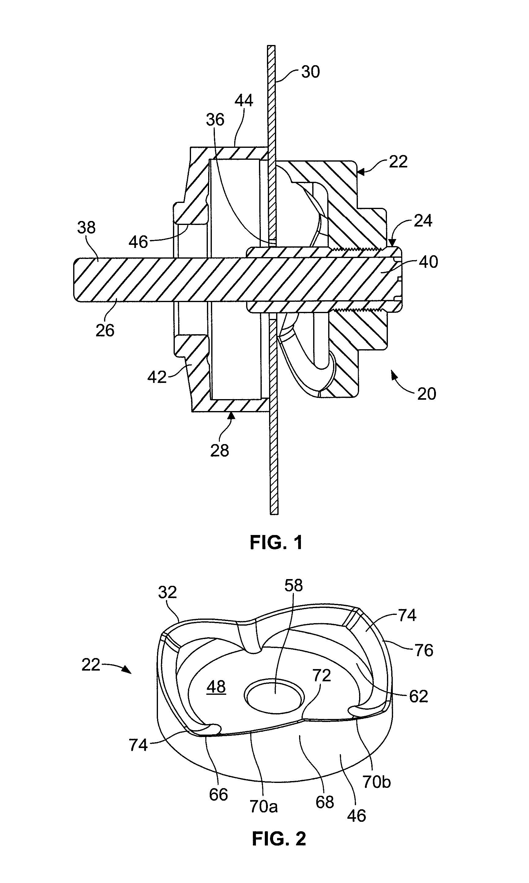
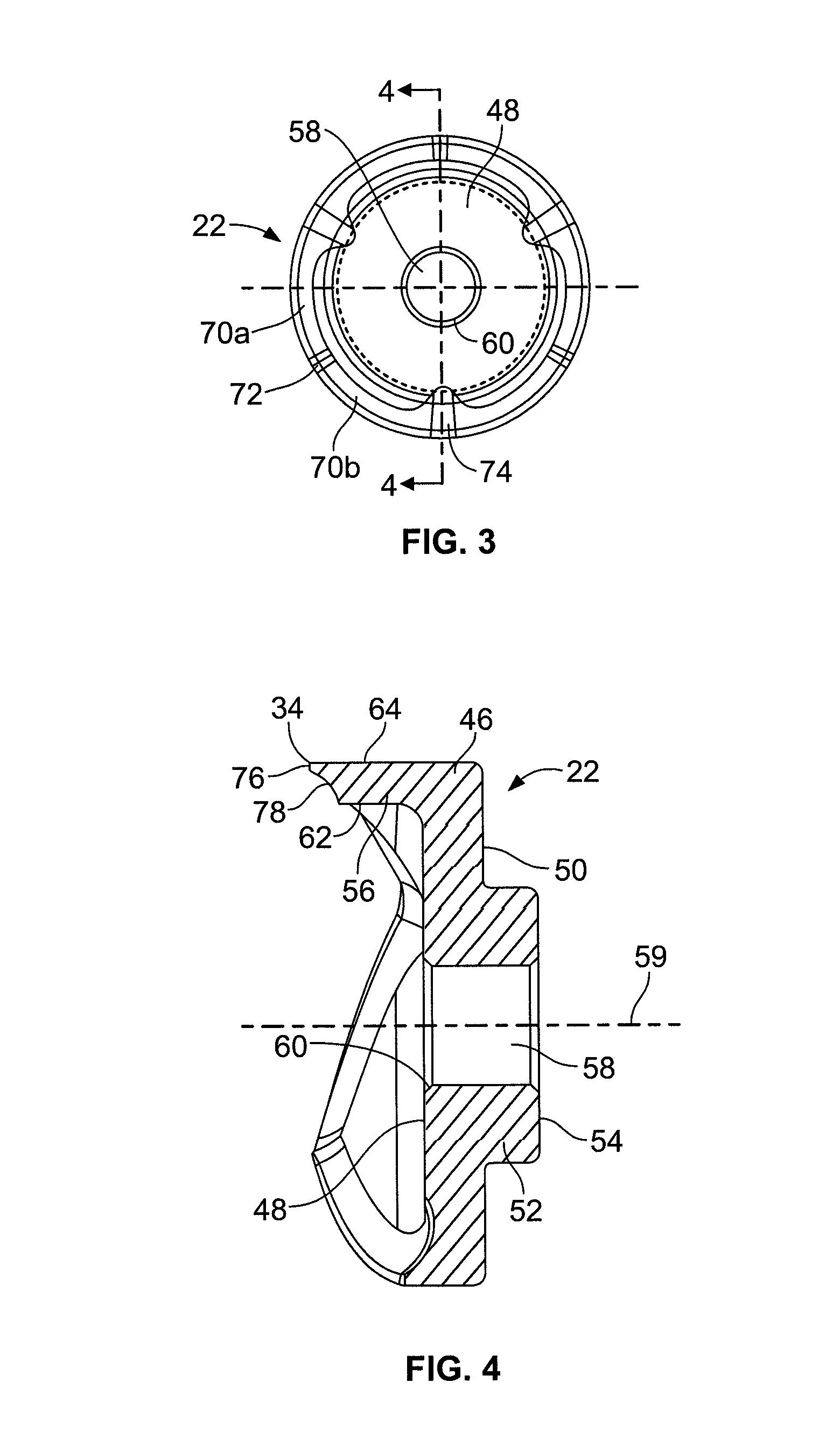
[0025]A punch assembly 20 is provided which includes a punch 22, a sleeve 24, a draw stud 26 and a die 28. The punch assembly 20 is used to punch a hole through a workpiece 30, such as metal, such as mild steel and stainless steel, fiberglass, plastic, etc. The punch assembly 20 is specially designed to also be able to punch 10-gauge stainless steel. The punch assembly 20 can be used to punch holes in the workpiece 30 up to 4.5″ diame...


PUM

PropertyMeasurementUnit
thickaaaaaaaaaa
included angleaaaaaaaaaa
angleaaaaaaaaaa

Abstract

A punch assembly includes a punch, a sleeve, a draw stud and a die. The sleeve adds rigidity to the draw stud, thereby reducing elastic deflection of the draw stud, reducing bending moment on the draw stud, reducing punching force, and extending the punch, draw stud and die fatigue life. The sleeve also aids in axial alignment of the punch, die and workpiece with a pilot hole drilled through a workpiece.

Description

[0001]This application claims the domestic benefit of provisional application Ser. No. 61 / 568,893, filed on Dec. 9, 2011, which disclosure is herein incorporated by reference in its entirety.FIELD OF THE INVENTION[0002]This invention is generally directed to a sleeve for a punch assembly for adding rigidity to a draw stud, and the method of use thereof.BACKGROUND OF THE INVENTION[0003]A punch is used in conjunction with a punch driver to punch holes in sheet metal, for example in the walls of electrical cabinets, aluminum, fiberglass and plastic. The punch is mounted on a sleeve, which in turn, is mounted on a draw stud.[0004]Generally, when a hole is to be punched in an electrical cabinet, a small hole is first drilled in the wall of the electrical cabinet. A first end of the draw stud is threaded into a ram of a hydraulic punch driver. A second end of the draw stud is inserted through a punching die and then through the drilled hole, the draw stud having a diameter that is less th...

Claims


Application Information

Patent Timeline
Patent Type & Authority Patents(United States)
IPC IPC(8): B26F1/14B21D28/34B23D35/00B26F1/38B23P11/00B26F1/44B26D3/00
CPCB26F1/14B23P11/00B26F1/386B21D28/343B26F1/44B23D35/004Y10T83/9425Y10T83/9476Y10T83/943Y10T83/9432Y10T29/49826Y10T83/06Y10T83/9428Y10T83/9423Y10T83/9437Y10T83/9435
Inventor NORDLIN, WILLIAM, F.
Owner GREENLEE TEXTRON
Why Eureka
Try Eureka