
Infrared signature matching system, control circuit, and related method

a technology of infrared signature matching and control circuit, applied in the field of infrared imaging, can solve problems such as the dependence of equipment on outside sources

Active Publication Date: 2014-12-09
NORTHROP GRUMMAN SYST CORP
View PDF28 Cites 4 Cited by
  • Summary
  • Abstract
  • Description
  • Claims
  • Application Information

AI Technical Summary

Problems solved by technology

Matching reflectivity of an object may be desirable for situations in which the user of IR imaging equipment relies on an outside IR source to illuminate the objects for detection; however, not all IR imaging equipment relies on outside IR sources to illuminate the objects for detection.

Method used


Image

  • Infrared signature matching system, control circuit, and related method
  • Infrared signature matching system, control circuit, and related method
  • Infrared signature matching system, control circuit, and related method

Examples


Embodiment Construction

[0013]In the following detailed description, reference is made to the accompanying drawings that form a part hereof and, in which is shown by way of illustration, specific embodiments in which the invention may be practiced. These embodiments are described in sufficient detail to enable those of ordinary skill in the art to practice the invention. It is to be understood that other embodiments may be utilized, and that structural, logical, and electrical changes may be made within the scope of the disclosure.

[0014]In this description, specific implementations shown and described are only examples and should not be construed as the only way to implement the present invention unless specified otherwise herein. It will be readily apparent to one of ordinary skill in the art that the various embodiments of the present invention may be practiced by numerous other partitioning solutions. For the most part, details concerning timing considerations and the like have been omitted where such d...


PUM


Abstract

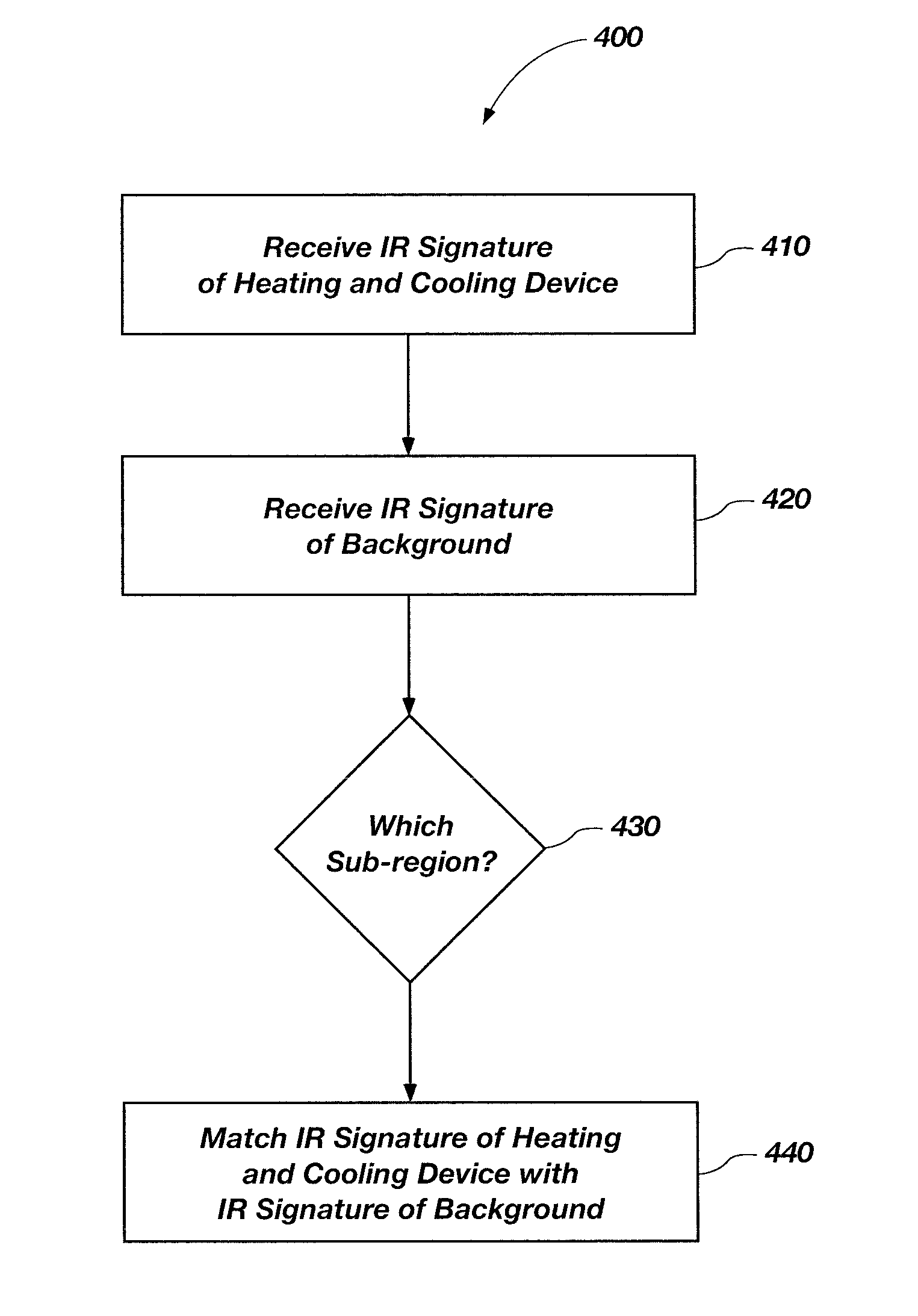
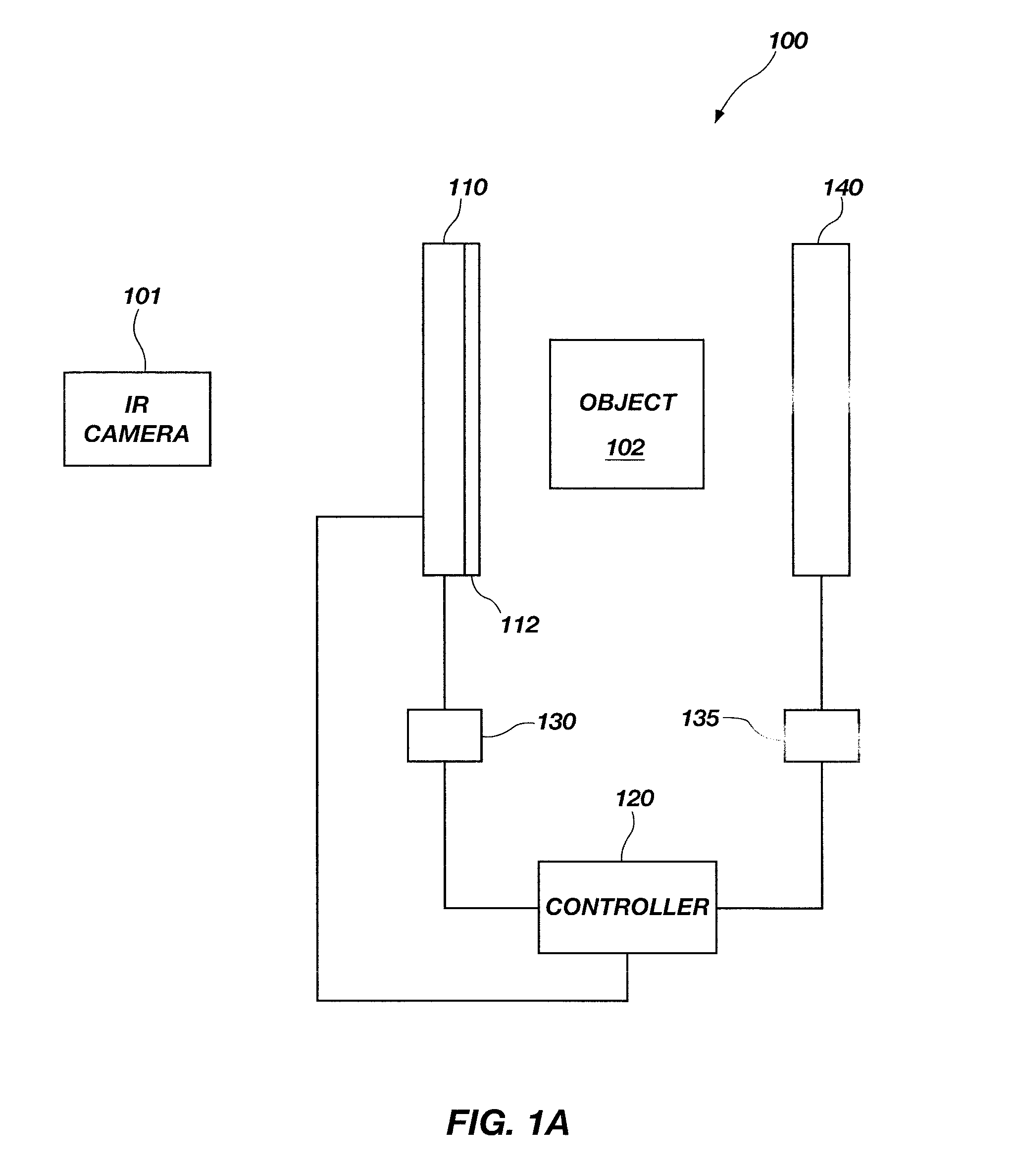
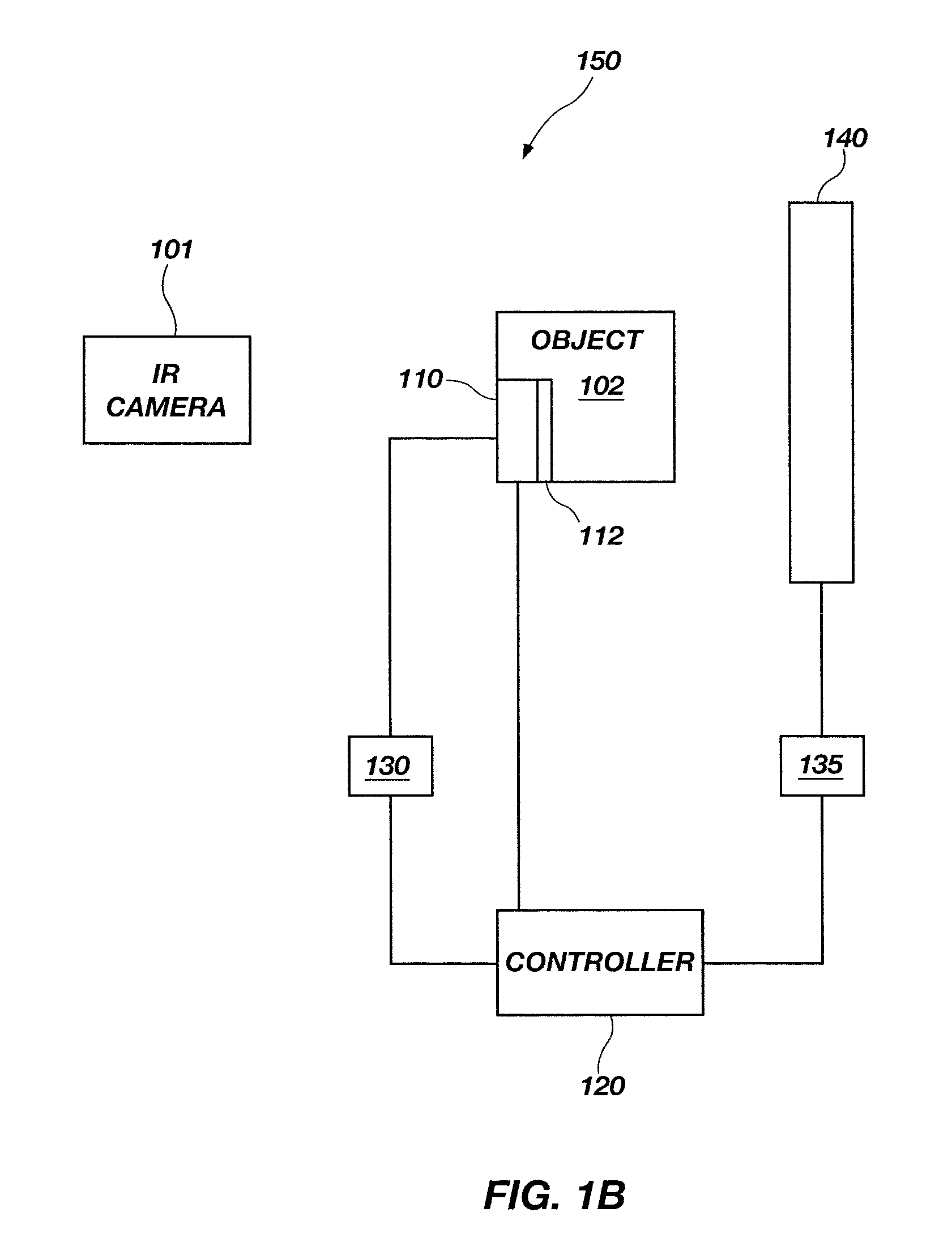
An infrared (IR) signature matching system comprises a heating and cooling device, a plurality of sensors configured to detect information related to the IR signature of the heating and cooling device and a background environment, a controller operably coupled with the heating and cooling device and the plurality of sensors. The controller is configured to receive the information from the plurality of sensors and adjust the temperature of the heating and cooling device until the IR signature of the heating and cooling device and the IR signature of the background environment are at least substantially matched in a selectable sub-region of the IR spectrum. Other systems, control circuits and related methods for matching IR signatures and cloaking objects in the IR spectrum are disclosed herein.

Description

TECHNICAL FIELD[0001]Embodiments of the present disclosure relate to infrared imaging and, more specifically, to a system, a control circuit, and a method related to matching infrared (IR) signatures of an object with an IR signature of a background environment.BACKGROUND[0002]IR imaging equipment (e.g., IR cameras) may be employed to capture information regarding IR emissions in the electromagnetic (EM) spectrum for environments of interest (EOI), and to make observations about objects of interest (OOI) or targets of interest (TOI) within those environments. An object (e.g., OOI, TOI, etc.) may be distinguished from its environment (i.e., background) by observing differences in the IR emissions between the object and its background (e.g., objects, materials, etc.). Because IR emissions are at least partially related to temperature of an object, the IR imaging equipment can indirectly measure the thermal profile of an object by detecting IR emissions within the field of view of the ...

Claims


Application Information

Patent Timeline
Patent Type & Authority Patents(United States)
IPC IPC(8): F41H3/00G05D23/00G05D23/27
CPCG05D23/2723F41H3/00G05D23/1928G05D23/27
Inventor OLSON, JARED K.CHILD, JAMESJACKSON, ROGERTETER, JARED S.CROCKER, EVAN
Owner NORTHROP GRUMMAN SYST CORP
Learn More