
Nylon polarized lens and moulding mold thereof

a polarized lens and nylon technology, applied in the field of nylon polarized lenses and moulding molds thereof, can solve the problems of lens breaking, lens color change, and inability to use popular frames, etc., to ensure the quality of products, increase work efficiency, and high price

Active Publication Date: 2014-12-16
XIAMEN HONGTAI ELECTRONICS OPTICAL C O
View PDF1 Cites 4 Cited by
  • Summary
  • Abstract
  • Description
  • Claims
  • Application Information

AI Technical Summary

Benefits of technology

This solution ensures the quality of thin nylon polarized lenses by preventing adhesive glue displacement, reducing material usage, and enhancing manufacturing efficiency, thereby increasing the yield rate and product level while addressing stress concentration and material compatibility issues.

Problems solved by technology

But, the PC lens doesn't have the property of anti-acidity, so it can't be used for popular frames.
The color of the edge of the lens may change, or the lens may break.
The PC material is not adapted for drilling.
This patent is not adapted to manufacture thin polarized lenses.

Method used


Image

  • Nylon polarized lens and moulding mold thereof
  • Nylon polarized lens and moulding mold thereof
  • Nylon polarized lens and moulding mold thereof

Examples


first embodiment

[0031]As shown in FIG. 8, the nylon polarized lens according to the present invention comprises a nylon material layer 100 and a polarized film 30. The nylon material layer 100 has four corners formed with positioning portions which are adapted to position the polarized film 30. The positioning portions may be in different embodiments. As shown in FIG. 8, the positioning portions are concaved portions 20. An outer surface of an area surrounded by the four concaved portions 20 is adapted to bond the polarized film 30. The feature of the present invention is that the nylon material layer 100 has buffer grooves 1 at two opposing end surfaces thereof.

[0032]As shown in FIG. 9 and FIG. 10, the moulding mold to manufacture the aforesaid nylon polarized lens comprises an upper die 60 and a lower die 40. The lower die 40 has a top surface which is an arc concave surface. Two opposing sides of the top surface of the lower die 40 are formed with buffer flanges 2 which are adapted to form the b...

second embodiment

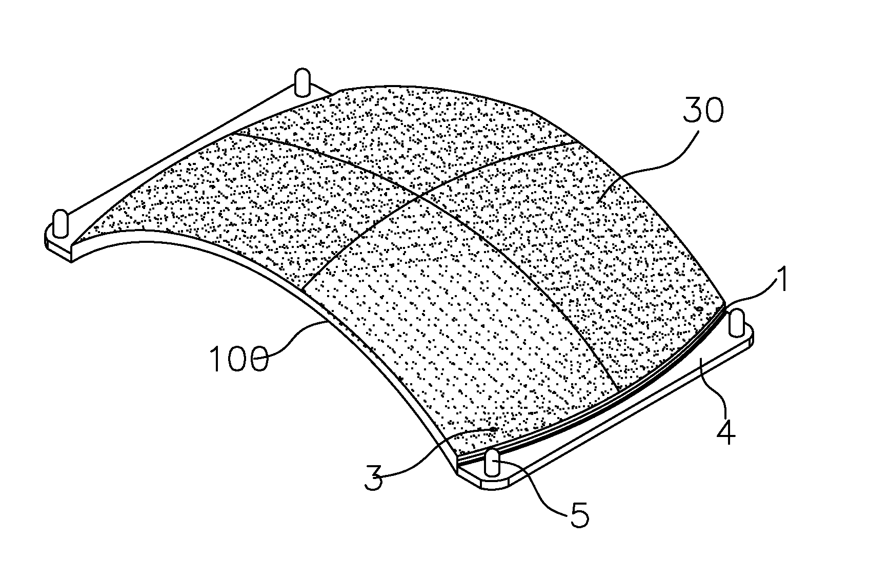
[0034]As shown in FIG. 11, the nylon polarized lens according to the present invention comprises a nylon material layer 100 and a polarized film 30. The nylon material layer 100 has four corners formed with positioning portions which are adapted to position the polarized film 30. In this embodiment, the positioning portions are apertures 3 formed at the four corners of the nylon material layer 100. The apertures 3 are for insertion of positioning needles of a mold to position the polarized film 30. The feature of the present invention is that the nylon material layer 100 has buffer grooves 1 at two opposing end surfaces thereof.

[0035]In this embodiment, the nylon material layer 100 has positioning flat surfaces 4 at two opposing sides thereof. The two positioning flat surfaces 4 have protrusions 5 formed at four corners of the two positioning flat surfaces 4. Through the protrusions 5, there is a gap between the stacked lenses to prevent the lenses from being damaged due to touching...


PUM

PropertyMeasurementUnit
thicknessaaaaaaaaaa
thicknessaaaaaaaaaa
sizeaaaaaaaaaa

Abstract

A nylon polarized lens includes a nylon material layer and a polarized film. The nylon material layer has four corners formed with positioning portions to position the polarized film. The nylon material layer has buffer grooves at two opposing end surfaces thereof. A moulding mold to manufacture a nylon polarized lens includes an upper die and a lower die. The lower die has a top surface which is an arc concave surface. Two opposing sides of the top surface of the lower die are formed with buffer flanges which are adapted to form buffer grooves of the nylon polarized lens. The top surface of the lower die is further formed with positioning portions to position the polarized film. The upper die has a bottom surface which is an arc convex surface. The upper die cooperates with the lower die to form a chamber for shaping the lens.

Description

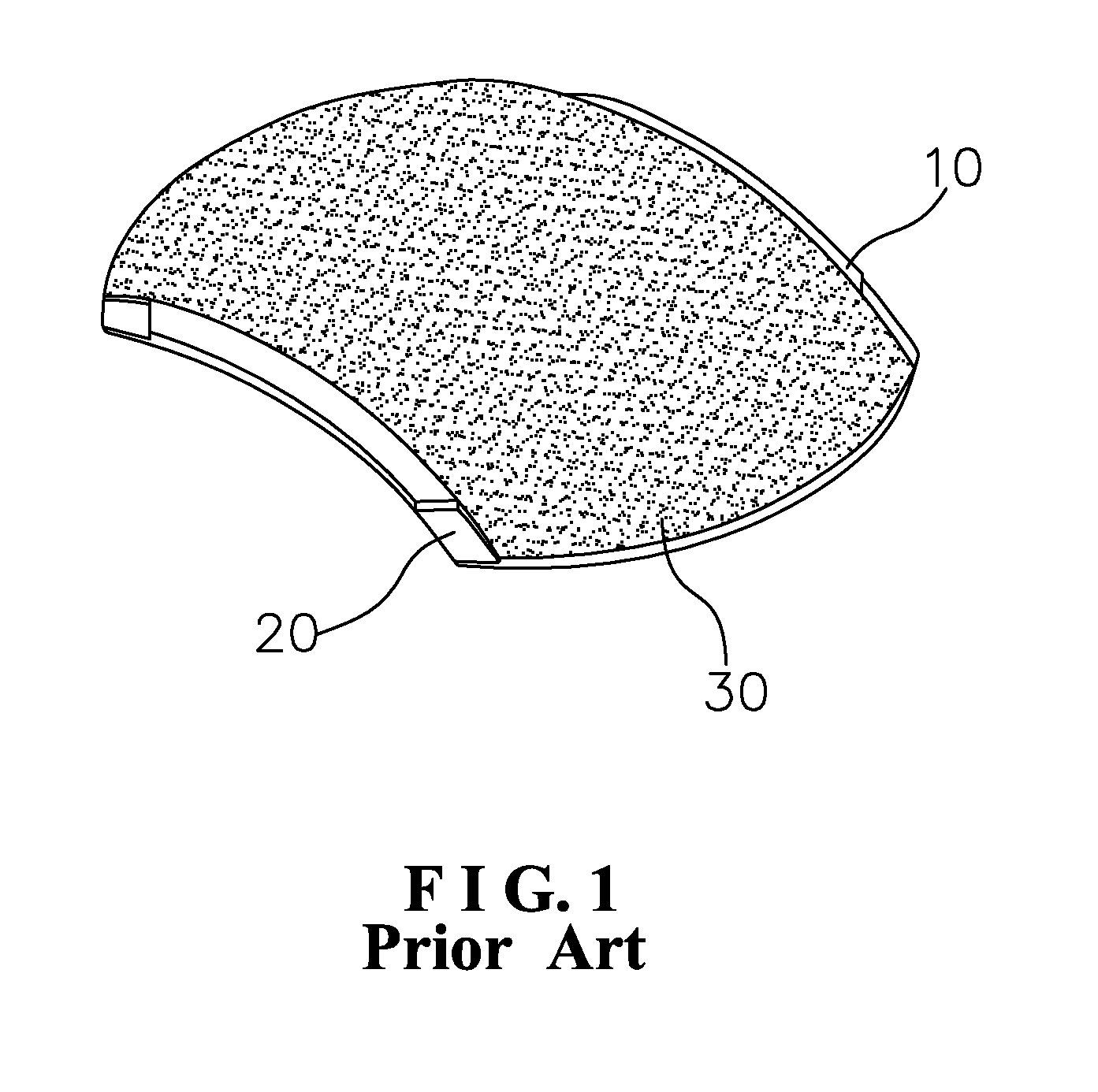
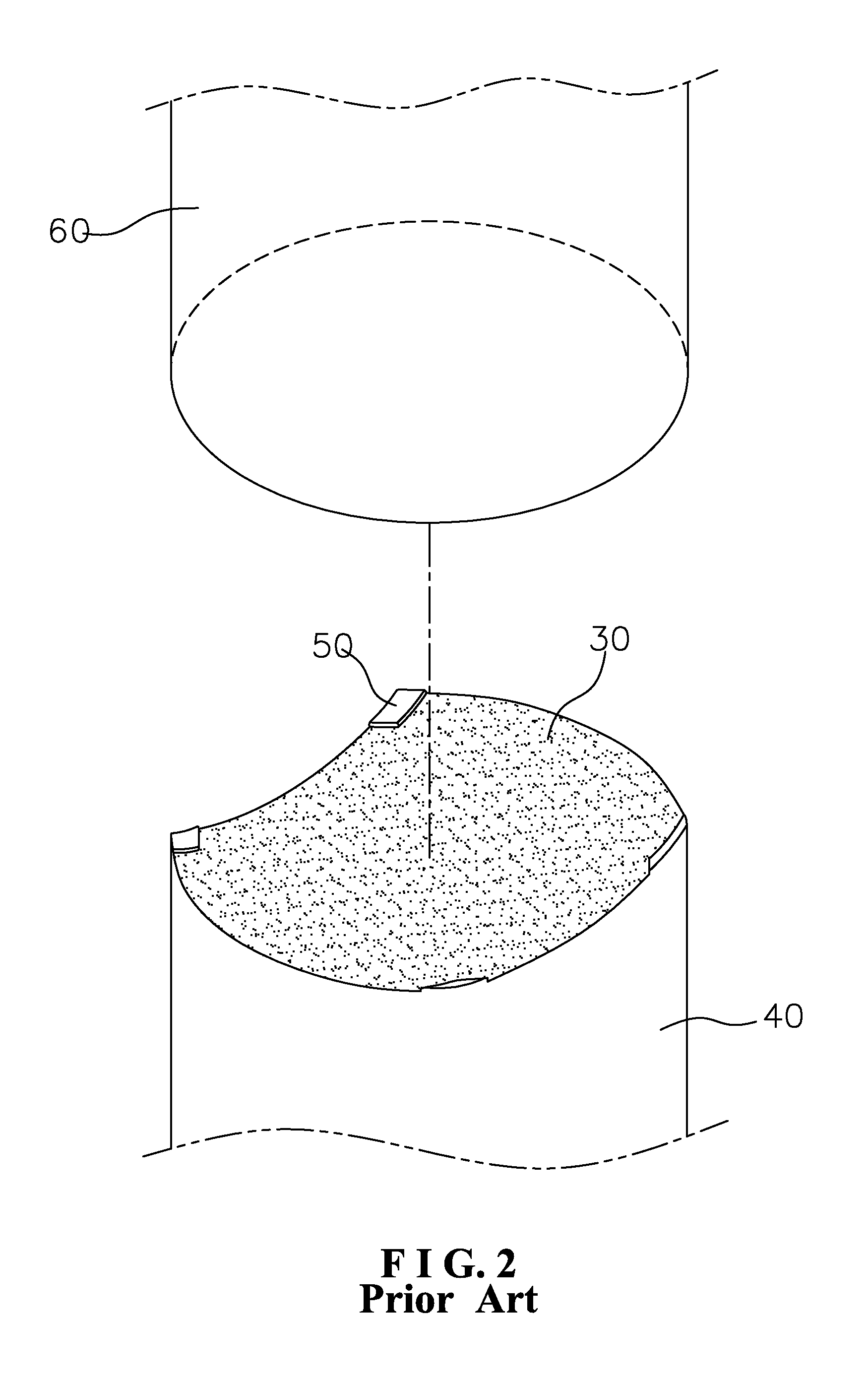
BACKGROUND OF THE INVENTION[0001]1. Field of the Invention[0002]The present invention relates to a nylon polarized lens and a moulding mold thereof.[0003]2. Description of the Prior Art[0004]Most conventional polarized lenses are made of PC material (polycarbonate) because the PC lenses are light, durable and environmental-friendly. The weight of the PC lens is about one tenth of the weight of a glass lens and half of the weight of a resin lens. The PC lens has the physical properties of anti-strike and anti-deformation, which won't break and is a safe lens. The thermosetting plastic can be recycled for other products. But, the PC lens doesn't have the property of anti-acidity, so it can't be used for popular frames. During injection, the PC polarized lens will is generate inner stress. When assembled to an eyeglasses frame, the PC lens has the phenomenon of stress concentration, particularly, to a metal frame. Even if it is not obvious when assembled, the phenomenon of stress conce...

Claims


Application Information

Patent Timeline
Patent Type & Authority Patents(United States)
IPC IPC(8): B29D11/00G02C3/00G02C7/12
CPCB29D11/00644B29D11/0048G02C7/12B29D11/0049B29D11/0073
Inventor CHEN, YU-HSIANG
Owner XIAMEN HONGTAI ELECTRONICS OPTICAL C O
Learn More