
Optical sensing system with a phase sensitive amplifier and associated methods

a phase sensitive amplifier and optical sensing technology, applied in the field of standoff sensing, can solve the problems of substantially noiseless amplification and add noise to the optical signal being amplified, and achieve the effect of substantial noise-free amplification and improved signal-to-noise ratio

Active Publication Date: 2014-12-16
HARRIS CORP
View PDF6 Cites 4 Cited by
  • Summary
  • Abstract
  • Description
  • Claims
  • Application Information

AI Technical Summary

Benefits of technology

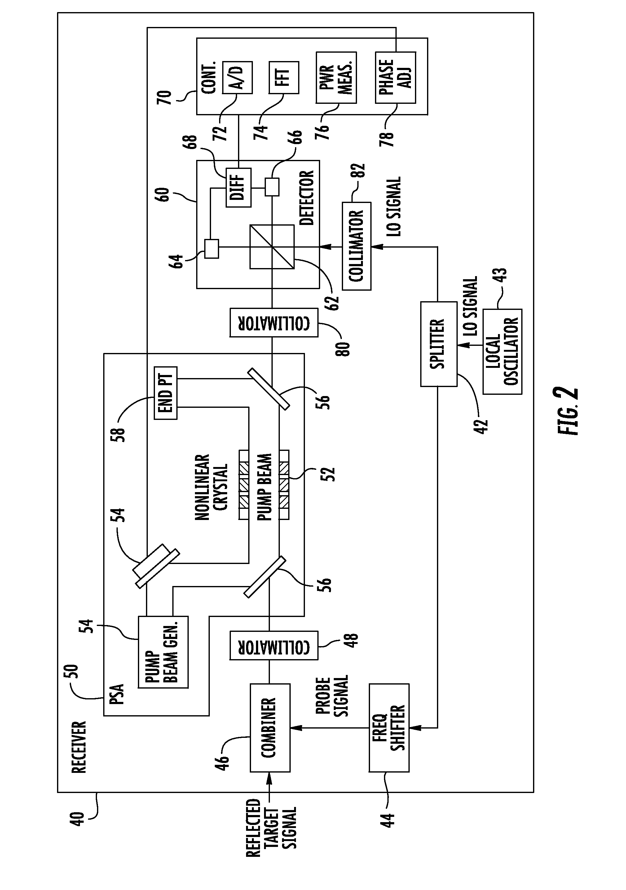
[0011]The PSA advantageously provides substantially noise-free amplification of the reflected free-space optical target signal. The PSA may be configured to periodically amplify the reflected free-space optical target signal in an amplifying quadrature, and periodically de-amplify the reflected free-space optical target signal in a de-amplifying quadrature by shifting a frequency of the optical target signal relative to a frequency of the PSA pump. Measuring the amplified quadrature of the PSA improves the signal-to-noise ratio.
[0012]To ensure that the amplified quadrature is being measured, the phase of the PSA is locked to a local oscillator signal. The optical sensing system may further comprise a combiner configured to combine the reflected free-space optical target signal and an optical probe signal to provide a combined optical signal. The optical probe signal has a known phase and amplitude, and is offset in frequency from the reflected free-space optical target signal and a local oscillator signal. This allows the optical probe signal to be discriminated from the reflected free-space optical target signal in the frequency spectral domain. The phase of the PSA may then be adjusted relative to the local oscillator signal so that an amplitude of the optical probe signal in the frequency spectral domain may be maximized. This may ensure that the reflected free-space optical target signal is being measured in the amplified quadrature of the PSA.

Problems solved by technology

However, a PIA adds noise to the optical signal being amplified.
However, there is a need to be able to operate a PSA with coherent detection so that amplification may be substantially noiseless.

Method used


Image

  • Optical sensing system with a phase sensitive amplifier and associated methods
  • Optical sensing system with a phase sensitive amplifier and associated methods
  • Optical sensing system with a phase sensitive amplifier and associated methods

Examples


Embodiment Construction

[0021]The present invention will now be described more fully hereinafter with reference to the accompanying drawings, in which preferred embodiments of the invention are shown. This invention may, however, be embodied in many different forms and should not be construed as limited to the embodiments set forth herein. Rather, these embodiments are provided so that this disclosure will be thorough and complete, and will fully convey the scope of the invention to those skilled in the art. Like numbers refer to like elements throughout.

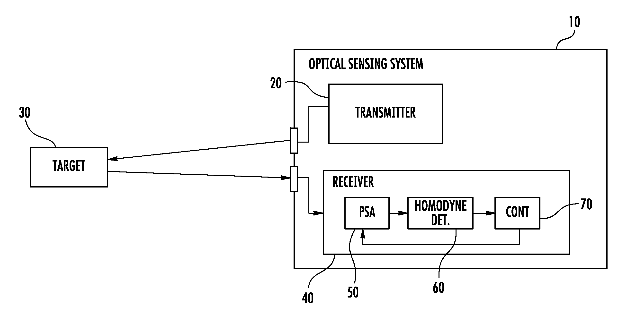
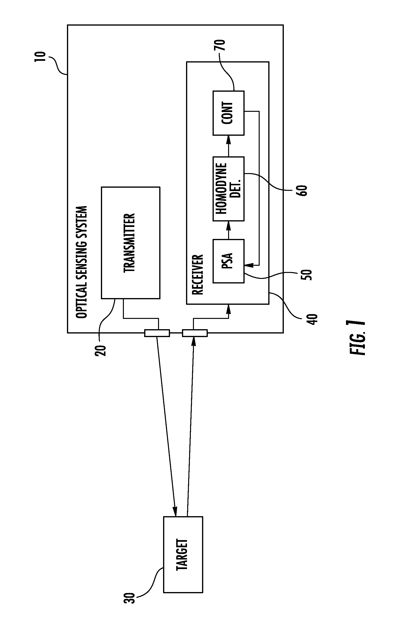
[0022]Referring initially to FIG. 1, an optical sensing system 10 includes a transmitter 20 and a receiver 40. The transmitter 20 is configured to transmit a free-space optical signal toward a target 30. The receiver 40 is configured to receive the free-space optical target signal reflected from the target 30. The receiver 40 includes a phase sensitive amplifier (PSA) 50, a homodyne detector 60 coupled downstream from the PSA, and a controller 70 configure...


PUM


Abstract

An optical sensing system includes a transmitter configured to transmit a free-space optical signal toward a target, and a receiver configured to receive a reflected free-space optical target signal from the target. The receiver includes a phase sensitive amplifier (PSA), a homodyne detector coupled downstream from the PSA, and a controller configured to adjust a phase of the PSA based upon the homodyne detector.

Description

GOVERNMENT LICENSE RIGHTS[0001]This invention was made with government support under Government Contract No. FA8750-09-C-0194 awarded by the National Institute of Standards and Technology (NIST). The U.S. Government may have certain rights in the invention.FIELD OF THE INVENTION[0002]The present invention relates to the field of standoff sensing, and more particularly, to an optical sensing system and method using a phase sensitive amplifier (PSA).BACKGROUND OF THE INVENTION[0003]Optical sensing systems may use optical amplifiers to compensate for signal attenuation. Two types of optical amplifiers are a phase insensitive amplifier (PIA) and a phase sensitive amplifier (PSA).[0004]An example PIA is an erbium-doped fiber amplifier. An advantage of a PIA is that signal gain is produced independent of the signal phase. This means that the phase of the PIA pump does not need to be locked to a local oscillator signal. However, a PIA adds noise to the optical signal being amplified.[0005]...

Claims


Application Information

Patent Timeline
Patent Type & Authority Patents(United States)
IPC IPC(8): H03F3/08
CPCH03F3/08
Inventor SMITH, KEVIN H.VISONE, CHRISTOPHER P.GLASSER, RYAN T.SILVER, MICHAEL L.BURBERRY, LEE M.WASILOUSKY, PETER A.
Owner HARRIS CORP
Learn More