
Fine step and large gain range programmable gain amplifier

Active Publication Date: 2005-06-30
AVAGO TECH INT SALES PTE LTD
View PDF3 Cites 3 Cited by
  • Summary
  • Abstract
  • Description
  • Claims
  • Application Information

AI Technical Summary

Benefits of technology

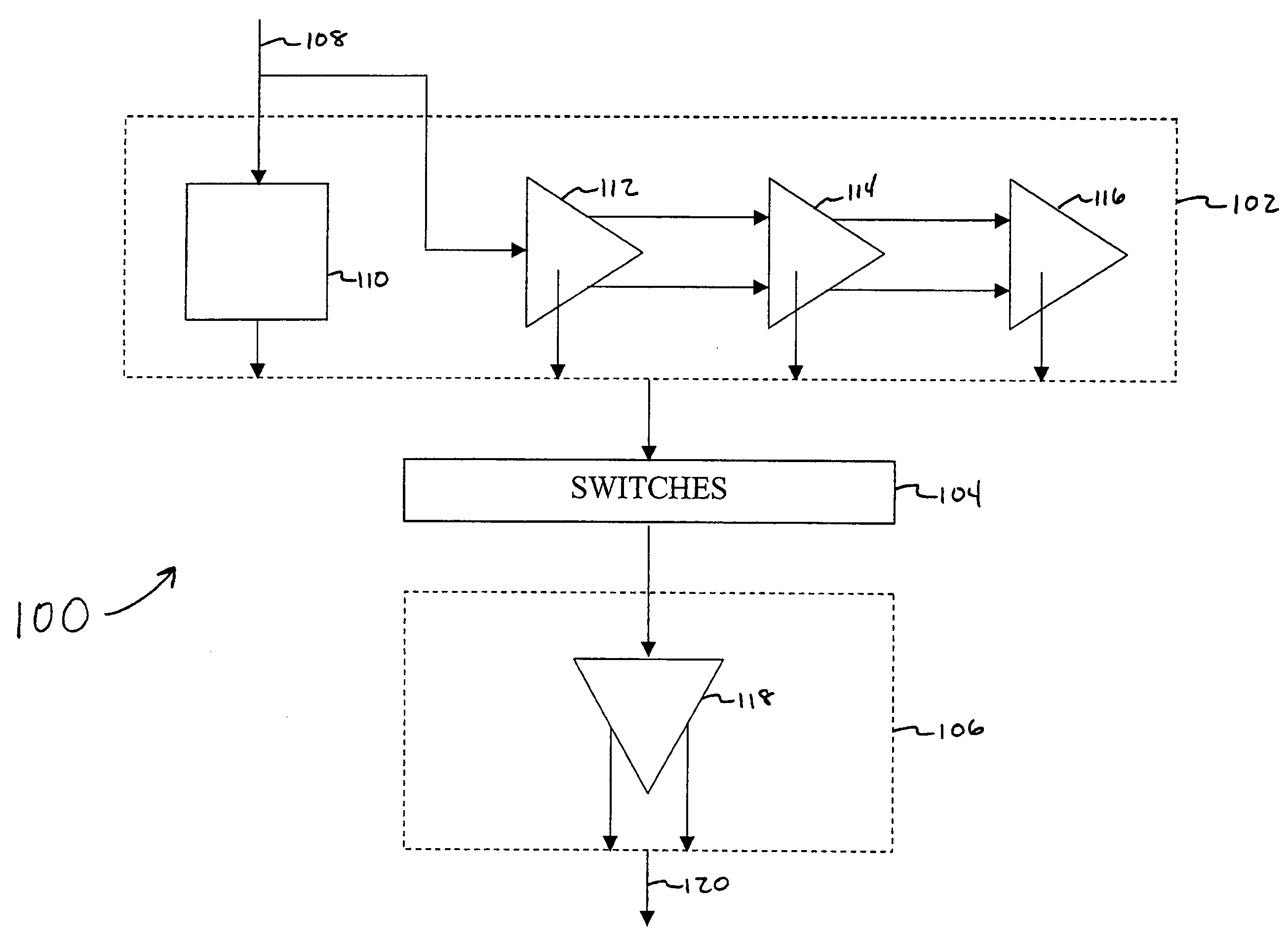
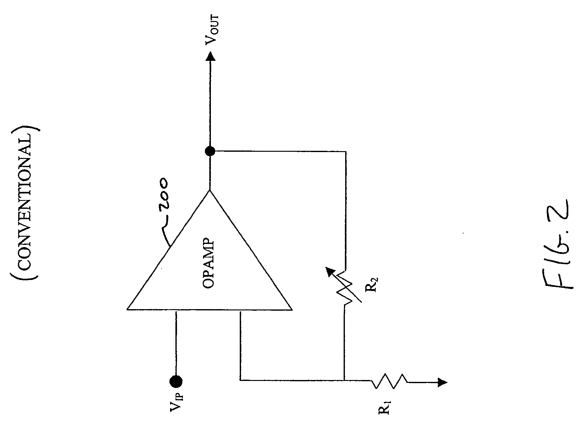
[0009] Each amplifier includes a feedback loop including an R / iR resistor ladder, wherein “i” represents the ratio of the resistors in the ladder. When an R / iR resistor ladder is configured inside a feedback loop, amplification can be achieved. In an embodiment, a 1 dB step is selected between the ladder stages. The feedback configuration allows the amplifier to have a high signal-to-noise ratio (SNR) and high linearity. Each resistor is connected to the plurality of switches as a tap. Depending on the resistor value, attenuation or amplification between each tap can be changed. Since there is a fixed amount of total resistance in the feedback loop, monotonicity is guaranteed when a different gain is selected using successive taps inside an amplifier. Besides improving monotonicity, the resistor network is unchanged when using different gain settings, as is the open-loop bandwidth of the amplifer. Hence, loop stability of the amplifier is maintained at all times.
[0010] The plurality of switches is broken into two sets of switches. In one embodiment, each set of switches closes only one switch at a time. The second stage accepts the output of two adjacent switches, one from each set of switches. The output of each of the two switches is an input gain signal for the second stage. In the second stage, also called an interpolation stage, a final output gain signal is interpolated between the two input gain signals. To do this, the input gain signals are amplified by corresponding differential amplifiers in the second stage. The differential amplifier is configured in a closed-loop feedback form and with current interpolation inside the feedback loop to provide high linearity, low distortion and high SNR for the signal. A plurality of switchable current sources provide tail current for each of the differential transistor pairs, configured inside a feedback loop, so that the contribution from each input signal is controlled by the number of current sources that are activated for each respective differential pair. As the current through a differential pair is increased, the output from that corresponding pair increases, thus increasing the contribution of the corresponding input signal to the output gain signal of the second stage.
[0013] In another embodiment, an amplification system using the PGA described above amplifies a signal partly in analog and partly in digital. In typical systems, an analog-to-digital converter (ADC) can limit the quality of the system because of the signal-to-noise ratio it creates in the system. However, smaller signals can tolerate a smaller SNR, and the ADC ceases to be the limiting factor. If the PGA of the present invention amplifies an input signal until the ADC is a step away from being the limiting factor, the amplified signal can be passed through the ADC without adding any additional noise to the system. The remainder of the desired gain can then be realized using a digital PGA.

Problems solved by technology

One of the complications with this method is that a glitch enters the output stream when all switches are open due to the transition between coarse steps.

Method used


Image

  • Fine step and large gain range programmable gain amplifier
  • Fine step and large gain range programmable gain amplifier
  • Fine step and large gain range programmable gain amplifier

Examples


Embodiment Construction

[0029] Although the examples contained herein typically refer to an increasing gain, one skilled in the art would recognize that the same techniques and systems may be used for decreasing gain.

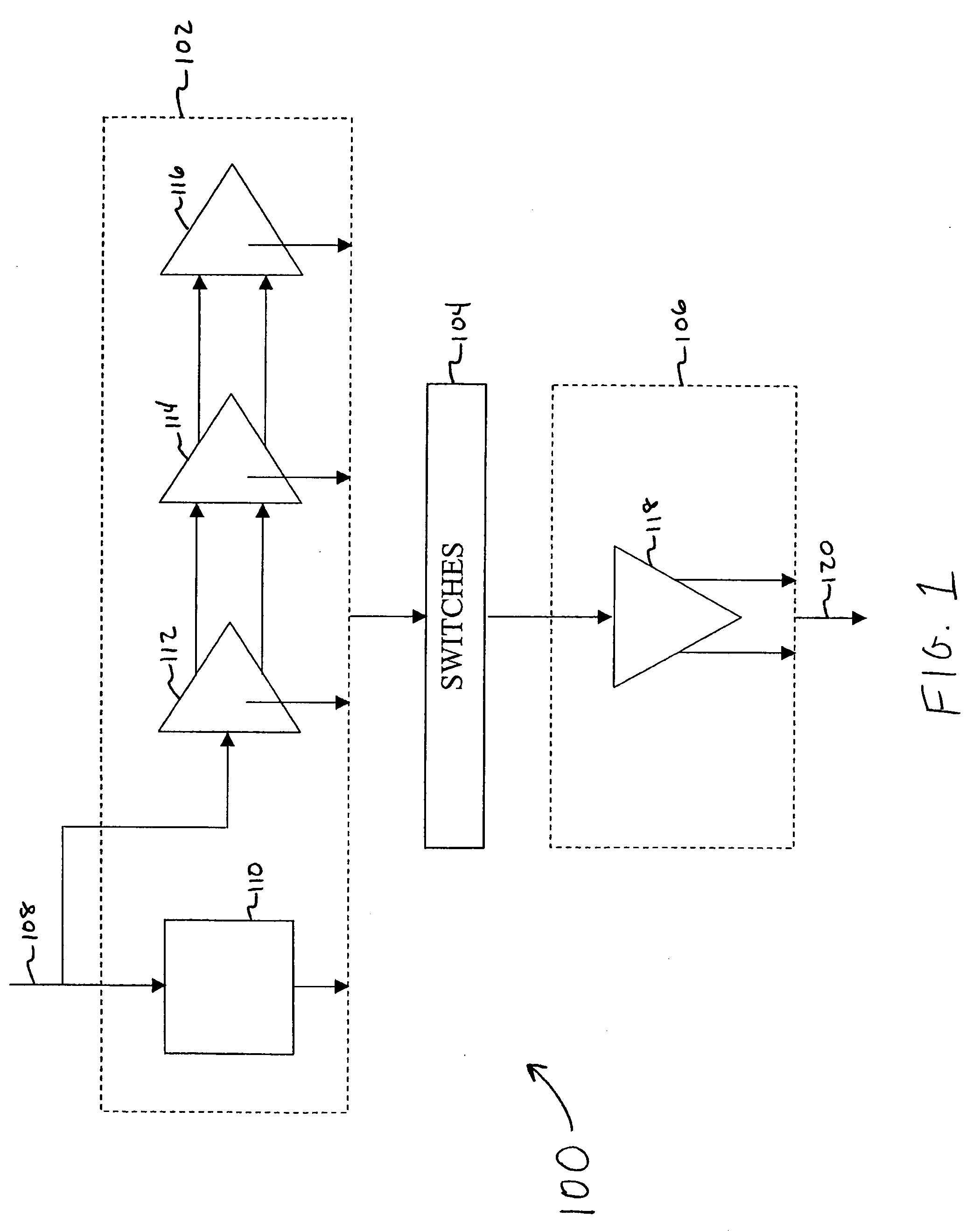
[0030]FIG. 1 is a block diagram of a programmable gain amplifier (PGA) 100 according to the present invention. PGA 100 comprises a first stage 102, a plurality of switches 104, and second stage 106. First stage 102 amplifies or attenuates an input signal 108 in a stepped fashion. In an embodiment, first stage 102 comprises an attenuator 110 and amplifiers 112, 114, and 116.

[0031] Although three amplifiers are shown here, additional amplifiers may be added or subtracted. In other words, the system can include attenuators only, amplifiers only, or combinations of both. Attenuator 110 is connected in parallel to amplifier 112 so that input signal 108 is received in parallel.

[0032] Amplifiers 112, 114, and 116 are connected to each other in series.

[0033] In an embodiment, amplifiers 112, 114, ...


PUM


Abstract

A programmable gain amplifier with three stages uses fine steps, has a large gain range, and is monotonic. The first stage comprises several amplifiers, each including a resistive feedback loop. The feedback loop comprises a series of resistors, with each resistor acting as a tap. Since the number of resistors in the loop is unchanging, monotonicity and stability is guaranteed when resistance is increased using successive taps. A switch system connects two taps at a time to an interpolation stage. Each of these taps corresponds to a specific resistor level, and thus a gain level. The interpolation stage uses a plurality of current sources inside a feedback amplifier to control the interpolation, in order to provide fine gain steps.

Description

BACKGROUND OF THE INVENTION [0001] 1. Field of the Invention [0002] The present invention is related to a programmable gain amplifier, and more specifically to a programmable gain amplifier used in an IF demodulator. [0003] 2. Related Art [0004] Programmable gain amplifiers (PGAs) are used in various analog signal processing applications where an electrical signal of varying amplitude must be either amplified or attenuated before subsequent signal processing. [0005] Various gain and / or attenuation settings are required to accommodate the wide dynamic range needed for the amplifier's input stages. [0006] In a typical automatic gain control (AGC) system, a PGA should be monotonic in order to maintain stability for the AGC loop, or simply to ensure the control circuit functions properly. [0007] In an IF demodulator or TV system, a programmable gain amplifier needs to have a large bandwidth to accommodate the high frequency nature of the input signal. An amplifier also needs to have a h...

Claims


Application Information

Patent Timeline
IPC IPC(8): H03G1/00H03G3/10
CPCH03G1/0088
Inventor TAM, DEREK HING-SANGVENES, ARDIE
Owner AVAGO TECH INT SALES PTE LTD
Learn More