Video signal processing device, video signal processing method, and non-transitory computer readable medium storing image processing program

Active Publication Date: 2011-06-16
RENESAS ELECTRONICS CORP
View PDF12 Cites 2 Cited by
  • Summary
  • Abstract
  • Description
  • Claims
  • Application Information

AI Technical Summary

Benefits of technology

[0008]The present inventor has found a problem that in the frame rate conversion disclosed in Japanese Unexamined Patent Application Publication Nos. 2008-118505 and 2006-304266, when motion compensation is performed on the input video signal that has been incorrectly converted, the effect of the incorrect conversion becomes more significant. Frame rate conversion is a technique that generates an interpolation frame to be inserted between a plurality of frames including an input video signal, based on the plurality of frames. More specifically, in the frame rate conversion, basically, pixels forming the plurality of frames to be referred to are correlated with each other by a motion vector, to thereby generate pixels forming an interpolation frame by using the pixels correlated with each other by the motion vector. Accordingly, if the plurality of frames to be referred to when an interpolation frame is generated has pixel information different from the original pixel information (e.g.,

Problems solved by technology

The present inventor has found a problem that in the frame rate conversion disclosed in Japanese Unexamined Patent Application Publication Nos. 2008-118505 and 2006-304266, when motion compensation is performed on the input video signal that has been incorrectly converted, the effect of the incorrect conversion becomes more significant.
Thus, the interpolation frame is not formed of correct pixels, and a moving image to be displayed including the interpolation frame includes a larger number of erroneous images to be displayed.
As a result, it is impossible to obtain the effect of the frame rate conversion that a t

Method used


Image

  • Video signal processing device, video signal processing method, and non-transitory computer readable medium storing image processing program
  • Video signal processing device, video signal processing method, and non-transitory computer readable medium storing image processing program
  • Video signal processing device, video signal processing method, and non-transitory computer readable medium storing image processing program

Examples


first exemplary embodiment

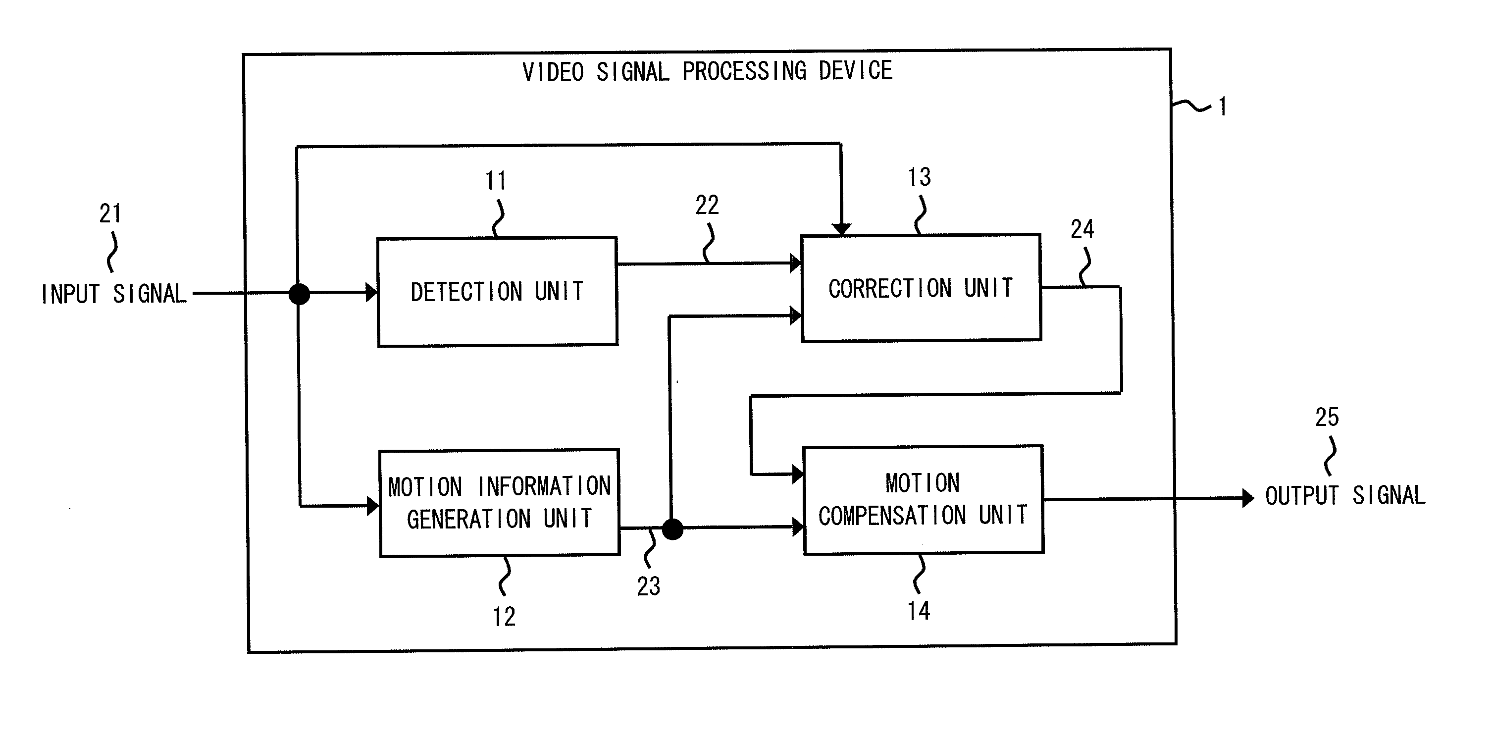
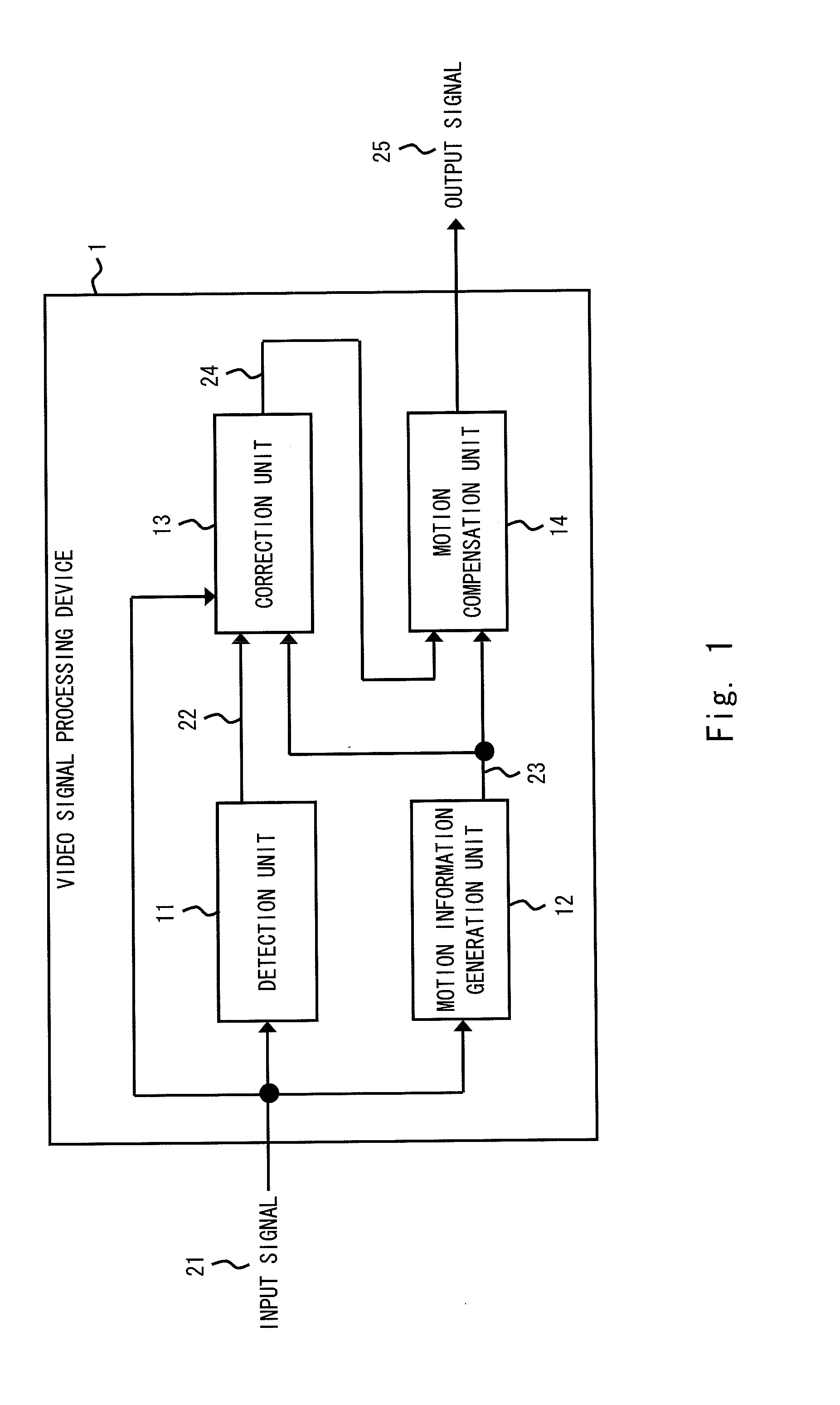
[0027]FIG. 1 is a block diagram showing an exemplary configuration of a video signal processing device 1 according to a first exemplary embodiment of the present invention. The video signal processing device 1 includes a detection unit 11, a motion information generation unit 12, a correction unit 13, and a motion compensation unit 14.

[0028]The detection unit 11 detects an accuracy 22 of conversion before input of an input signal 21 which is an input video signal. Specifically, the input signal 21 is a moving image representing a motion to be displayed by sequentially displaying a plurality of frames in succession. The frames are sequentially input to the detection unit 11. After that, the detection unit 11 detects the accuracy of conversion in units of processing (e.g., a plurality of lines or entire frame) per frame. An example of the accuracy of conversion is a ratio of erroneous pixels, which are different from the correct pixels, to the entire pixels corresponding to the unit o...

second exemplary embodiment

[0036]FIG. 3 is a block diagram showing an exemplary configuration of a video signal processing system 3 according to a second exemplary embodiment of the present invention. The video signal processing system 3 receives an input video signal 41 from an external device (not shown), performs a predetermined conversion processing, and outputs an output video signal 49 to a display device 4. The input video signal 41 is, for example, a moving image representing a target motion by sequentially displaying a plurality of frames in succession. The plurality of frames are sequentially input to the image processing system 3. The video signal processing system 3 can receive video signals from various external devices via input terminals (not shown). The video signal processing system 3 can accept both interlaced and progressive signals. The interlaced signal is a signal in which pixels in each line of a frame are sent by alternately scanning the odd-numbered lines and even-numbered lines, for ...

third exemplary embodiment

[0095]A third exemplary embodiment of the present invention is an exemplary embodiment in which the motion compensation unit for FRC 57 included in the FRC system 34 according to the second exemplary embodiment is replaced with a motion compensation unit for MJC (Movie Judder Cancellation) 57a. The MJC, which is one type of motion compensation, is a technique that displays 120 images of 24 movie films per second, thereby achieving a smooth display of motions without causing a unique jumpy motion. The configuration and operation of the third exemplary embodiment may be similar to of those of the second exemplary embodiment, so the detailed description and illustration thereof are omitted.

[0096]FIG. 11 is a diagram illustrating the principle of image output and reproduction in an MJC system. An MJC system 92 shown in FIG. 11 is an exemplary system for performing MJC processing on an input video signal. The MJC system 92 receives video signals in the order of the frames FIA, FIB, and F...


PUM


Abstract

A video signal processing device includes: a correction unit which performs correction such that when a first frame to be displayed at a first time includes a pixel different from a pixel to be included in the first frame, the pixel different from the pixel to be included in the first frame is corrected to the pixel to be included in the first frame, and when a second frame to be displayed at a second time prior to the first time includes a pixel different from a pixel to be included in the second frame, the pixel different from the pixel to be included in the second frame is corrected to the pixel to be included in the second frame; and a motion compensation unit which generates an interpolation frame to be displayed at a time between the first and second times by referring to the first and second frames.

Description

INCORPORATION BY REFERENCE[0001]This application is based upon and claims the benefit of priority from Japanese patent application No. 2009-281493, filed on Dec. 11, 2009, the disclosure of which is incorporated herein in its entirety by reference.BACKGROUND[0002]1. Field of the Invention[0003]The present invention relates to a video signal processing device, a video signal processing method, and a non-transitory computer readable medium storing a video signal processing program. In particular, the present invention relates to a video signal processing device, a video signal processing method, and a non-transitory computer readable medium storing a video signal processing program for performing motion estimation and motion compensation of a video signal to be input.[0004]2. Description of Related Art[0005]Japanese Unexamined Patent Application Publication No. 2008-118505 discloses a technique relating to a frame rate converter (FRC) of motion compensation type. Frame rate conversion...

Claims


Application Information

Patent Timeline
IPC IPC(8): H04N5/21
CPCH04N7/014H04N7/0132
Inventor SHAO, MING
Owner RENESAS ELECTRONICS CORP
Why Eureka
Try Eureka