
Automatic vehicle exterior light control system assemblies

a vehicle and control system technology, applied in the direction of lighting and heating equipment, lighting support devices, instruments, etc., can solve the problems of repeatable and predictable vehicle to vehicle system operation, and achieve the effect of accurate detection of related images

Active Publication Date: 2014-12-16
GENTEX CORP
View PDF70 Cites 16 Cited by
  • Summary
  • Abstract
  • Description
  • Claims
  • Application Information

AI Technical Summary

Benefits of technology

This patent text describes automatic vehicle exterior light control systems that can detect related images accurately and adjust their lighting accordingly. The system includes an imager assembly mounting means that ensures accurate alignment and proper selection for the specific vehicle requirements. The mounting means is also designed to be quick and easy to install, and can be manufactured using snap-together components with minimal tools required. Additionally, the patent text mentions the integration of various improvements with other vehicular systems, which can lead to better overall operational performance and cost-effectiveness.

Problems solved by technology

It has become apparent that repeatable and predictable vehicle to vehicle system operation suffers when misalignment is present in the corresponding imaging assemblies.

Method used


Image

  • Automatic vehicle exterior light control system assemblies
  • Automatic vehicle exterior light control system assemblies
  • Automatic vehicle exterior light control system assemblies

Examples


Embodiment Construction

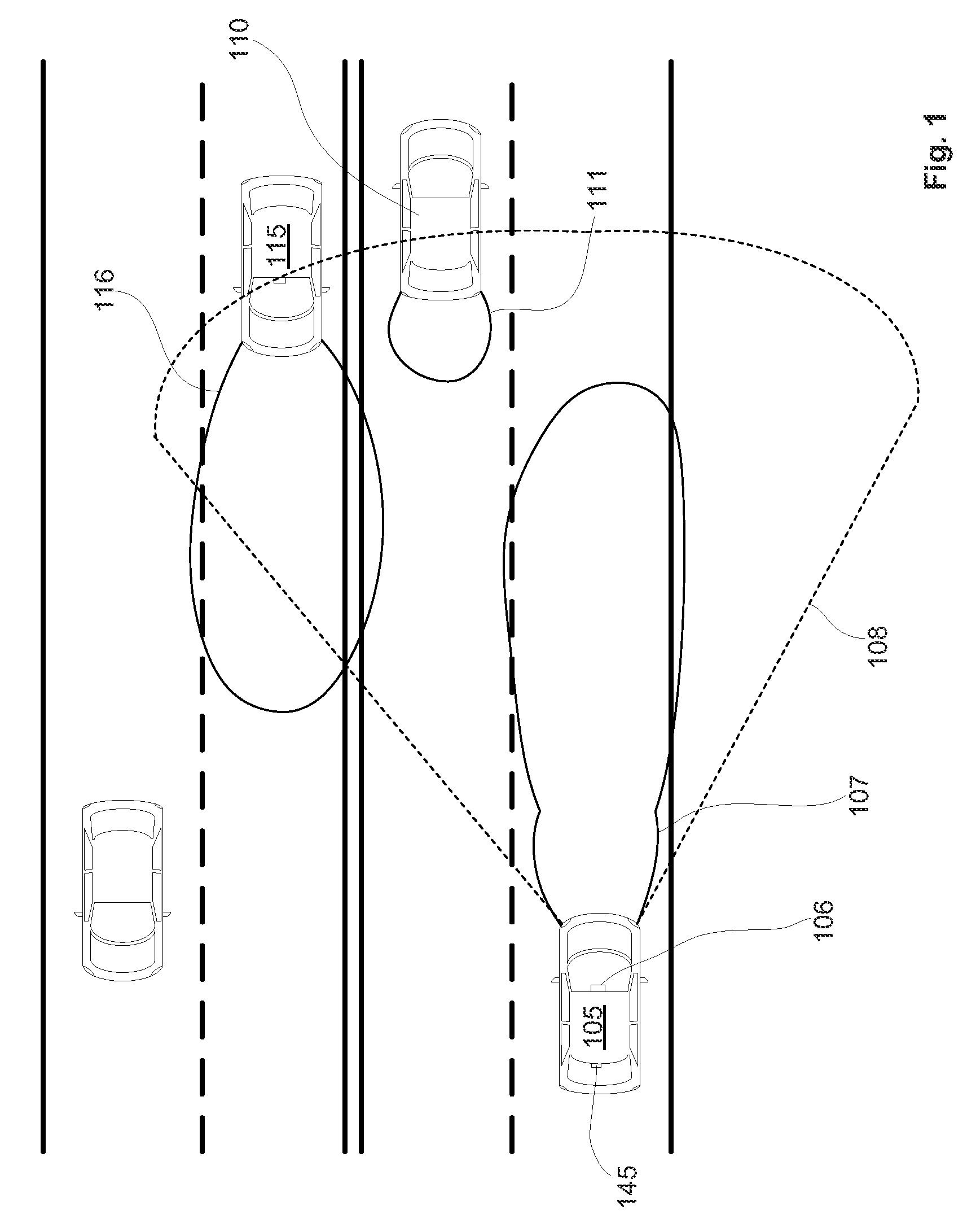
[0033]Referring initially to FIG. 1, for illustrative purposes, an automatic vehicle exterior light control system 106 is shown to be installed within a controlled vehicle 105. Although the control system 106 is depicted to be integral with the interior rearview mirror assembly, it should be understood that the control system, or any of the individual components thereof, may be mounted in any suitable location within the interior, or on the exterior, of the controlled vehicle 105. The term “controlled vehicle” is used herein with reference to a vehicle comprising an automatic vehicle exterior light control system. Suitable locations for mounting the associated image sensor are those locations that provide an unobstructed view of the scene generally forward of the controlled vehicle 105 and allow for detection of headlights 116 of oncoming vehicles 115 and taillights 111 of leading vehicles 110 within the glare zone 108 associated with the controlled vehicle.

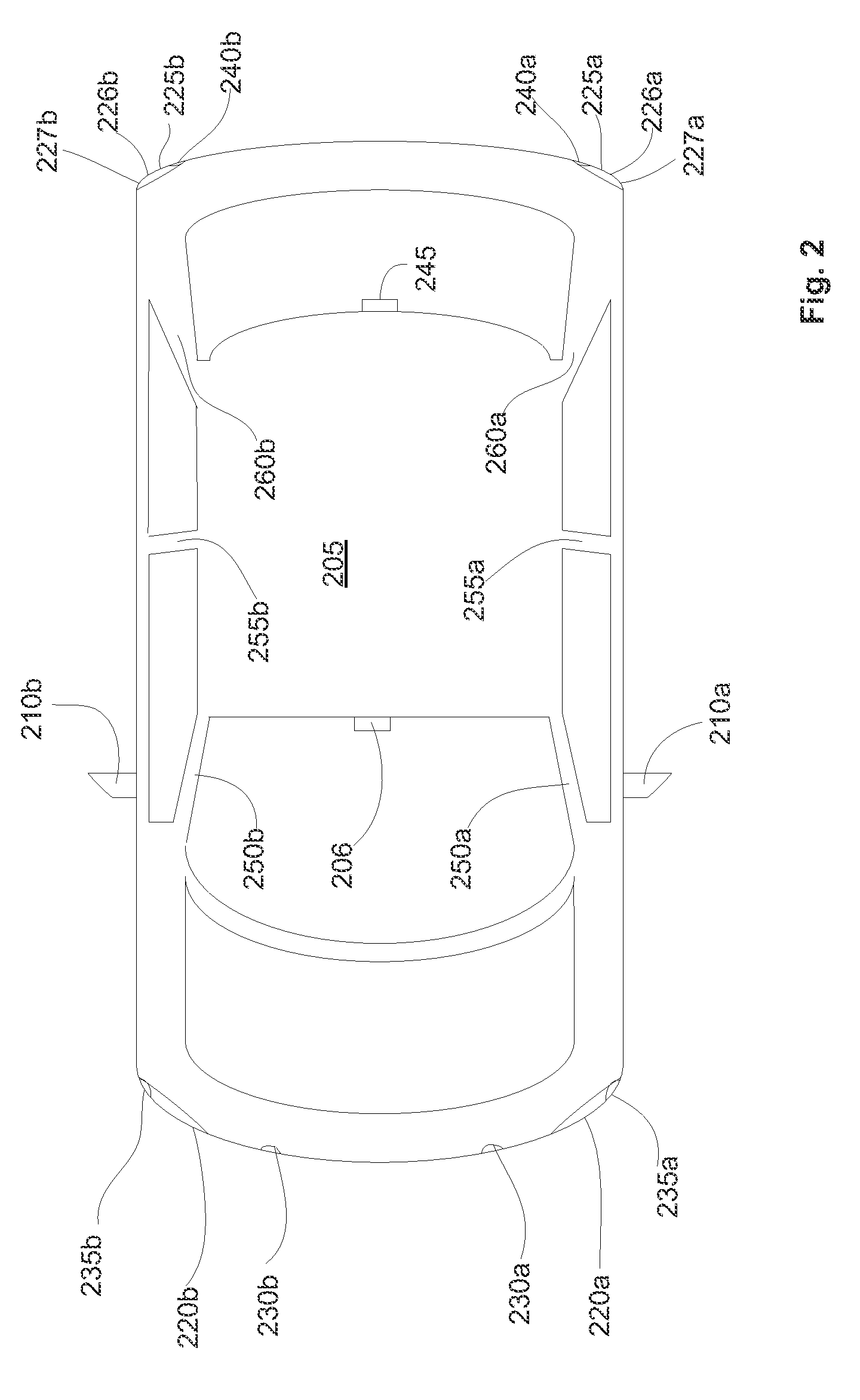
[0034]FIG. 2 depicts a co...


PUM


Abstract

The present invention relates to various improvements relating to automatic vehicle equipment control systems.

Description

CROSS REFERENCE TO RELATED APPLICATIONS[0001]This application is a continuation of U.S. patent application Ser. No. 10 / 783,273 filed Feb. 20, 2004, and now published as U.S. Pat. App. Publ. No. 2004 / 0164228, which claims priority, under 35 U.S.C. §119(e), to U.S. provisional patent application Ser. No. 60 / 448,793, filed on Feb. 21, 2003. The disclosure of the above mentioned applications are hereby incorporated herein in their entirety by reference.BACKGROUND OF THE INVENTION[0002]Automatic vehicle exterior light control systems provide a significant convenience function for drivers by alleviating the burden of manually switching between high and low beam headlights in response to changing traffic conditions. It is known that drivers, on average, do not utilize their high beam headlights as often as is appropriate. High beam headlights can provide from two to four, or more, times the visibility distance at night as compared to low beam headlights. Thereby, a driver of a controlled v...

Claims


Application Information

Patent Timeline
Patent Type & Authority Patents(United States)
IPC IPC(8): B60R1/12H01L27/00F21S8/10H01J5/02B60Q1/14B60L
CPCB60R2001/1223B60Q1/1423F21S48/17B60R2001/1253F21S41/60B60Q1/04H01L27/00B60Q1/08
Inventor FOGG, JEREMY A.EJSMONT, GREGORY M.TUTTLE, DARIN D.STAM, JOSEPH S.
Owner GENTEX CORP
Learn More