Electronic device cooling with microjet impingement and method of assembly

a technology of electronic devices and microjets, applied in semiconductor devices, semiconductor/solid-state device details, lighting and heating apparatus, etc., can solve the problems of increasing the weight and volume of electronic systems, unable to limit the temperature rise of today's complex electronic components, and high operating junction temperatur

Inactive Publication Date: 2014-12-16
GENERAL ELECTRIC CO
View PDF22 Cites 16 Cited by
  • Summary
  • Abstract
  • Description
  • Claims
  • Application Information

AI Technical Summary

Problems solved by technology

Many known heat removal systems for such electronic devices include a path for heat flow with a high thermal resistance resulting in a high operating junction temperature.
While considerable efforts have been made to develop heat removal systems that are reliable and efficient, these systems often only address the backside cooling of the electrical devices.
These systems are unable to limit the temperature rise of today's complex electronic components.
Such cooling solutions, where heat must be conducted away from components before rejection to the air, add considerable weight and volume to electronic systems.
This results in complex electronic systems that continue to grow in size and weight due to the inefficiencies of the current cooling system designs.

Method used


Image

  • Electronic device cooling with microjet impingement and method of assembly
  • Electronic device cooling with microjet impingement and method of assembly
  • Electronic device cooling with microjet impingement and method of assembly

Examples


Embodiment Construction

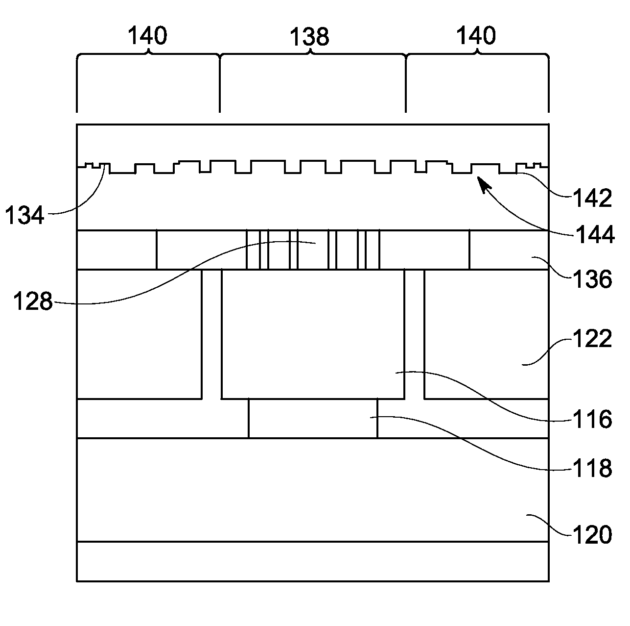
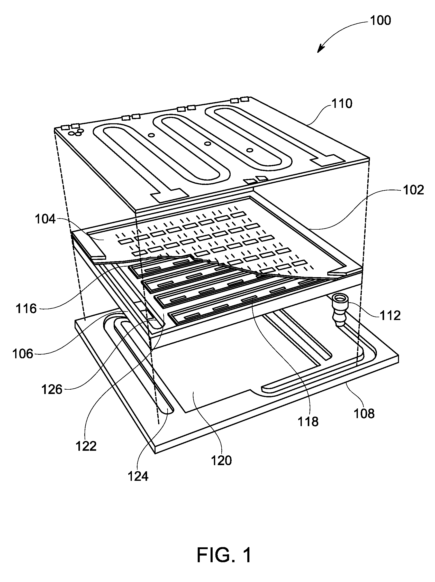
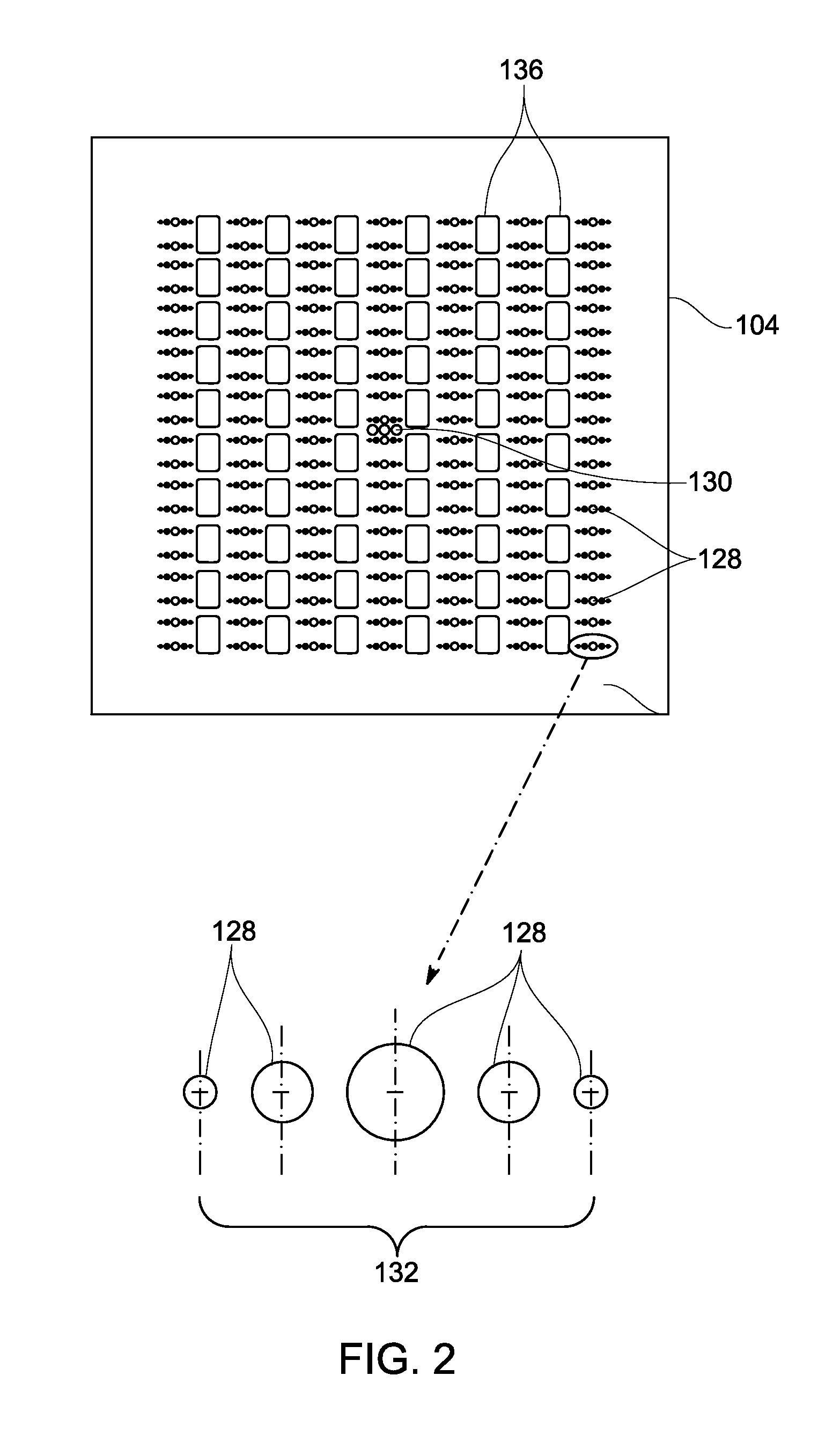
[0011]The apparatus, systems, and methods described herein relate to cooling integrated circuit (IC) devices. An intrachip micro-channel impingement cooler (MCIC) includes bringing microfluidic evaporative liquid cooling within about 100 micrometers (μm) of the heat source using micro-channel impingement cooling. In operation, a subcooled liquid, or cooling fluid, enters a reservoir that feeds channels configured to carry the cooling fluid to an array of microjets, which are etched into an injector plate that is offset a defined distance from the integrated circuit device. The high velocity liquid exiting from the microjets impinges on the heated surface of the die, where it provides cooling through both single-phase convection and boiling heat transfer. Nanoscale and microscale structures formed on the surface of the die substrate enhance nucleate boiling, heat transfer coefficient, and increase critical heat flux (CHF) to levels above those measured for an equivalent smooth surfac...


PUM


Abstract

An integrated circuit device including a die with a substrate with a first surface and a second surface opposite the first surface is provided. The die includes at least one circuit element positioned on the first surface. Formed on the second surface, is a wetting feature that includes an array of spaced-apart nanoscale structures and / or an array of spaced-apart microscale structures. The wetting feature also includes a wettability coating applied to at least a portion of the second surface. The integrated circuit device includes a spacer coupled to the die adjacent to the second surface. In addition, an injector plate is coupled to the spacer. The injector plate includes at least one microjet and at least one exit hole defined through the injector plate. The at least one exit hole is positioned adjacent to the at least one microjet.

Description

BACKGROUND[0001]The subject matter disclosed herein relates generally to cooling electronic devices and, more particularly, to methods and apparatus for dissipating heat from an integrated circuit device.[0002]In at least some known electronic systems, e.g., computers, radios, radar modules, etc., the electronic device is the warmest component in the system. As such, at least some known electronic devices are coupled to a heat removal system to dissipate heat generated by the electronic device. Many known heat removal systems for such electronic devices include a path for heat flow with a high thermal resistance resulting in a high operating junction temperature. Generally, waste heat is removed by conduction, spreading, and convection to an appropriate cooling fluid with gradual reductions in temperature as the heat moves from the heat source to the cooling fluid. For example, the heat generated by a high-density power integrated circuit (“IC”) device may travel from the front side...

Claims


Application Information

Patent Timeline
Patent Type & Authority Patents(United States)
IPC IPC(8): H01L23/473H01L23/34F28F13/18
CPCH01L23/4735F28F13/187H01L2924/0002H01L2924/00
Inventor DE BOCK, HENDRIK PIETER JACOBUSWEAVER, JR., STANTON EARLBAHADUR, RAJBROWNE, ERIC AYRESMANDRUSIAK, GARY DWAYNE
Owner GENERAL ELECTRIC CO
Why Eureka
Try Eureka