Specular edge extraction using multi-flash imaging

a multi-flash, imaging technology, applied in the field of computer vision, can solve the problems of object non-lambertian reflectance, object that is highly specular or has significant transparency cannot be handled by such methods, and the presense of threads complicates the problem, so as to avoid the effect of degeneracy in 3d line reconstruction

a multi-flash, imaging technology, applied in the field of computer vision, can solve the problems of object non-lambertian reflectance, object that is highly specular or has significant transparency cannot be handled by such methods, and the presense of threads complicates the problem, so as to avoid the effect of degeneracy in 3d line reconstruction

US8913825B2Inactive Publication Date: 2014-12-16MITSUBISHI ELECTRIC RES LAB INC

Image

  • Specular edge extraction using multi-flash imaging
  • Specular edge extraction using multi-flash imaging
  • Specular edge extraction using multi-flash imaging

Examples


Embodiment Construction

[0037]System Overview

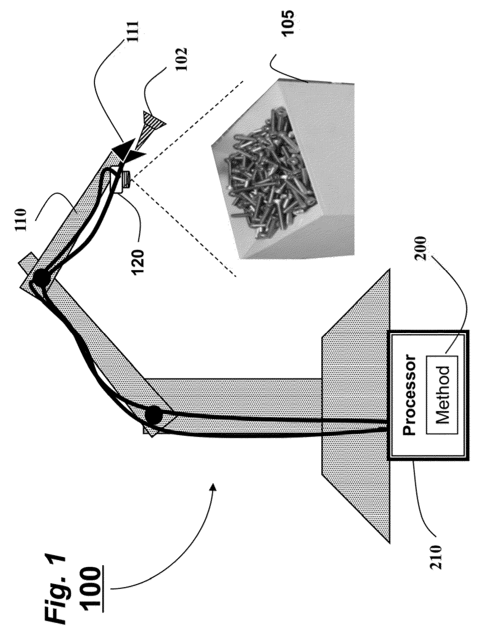
[0038]FIG. 1 shows a system 100 and method 200 for determining poses of objects according to embodiments of our invention. In particular the objects are metallic screws or bolts 102 arranged in a bin 105 of hundreds of identical or different kinds of objects. Since the objects have shiny surfaces, the objects appear specular when illuminated. This makes it difficult to detect the objects in images of the scene, because the objects reflect the surrounding environment, and the textureless objects themselves are difficult to discern.

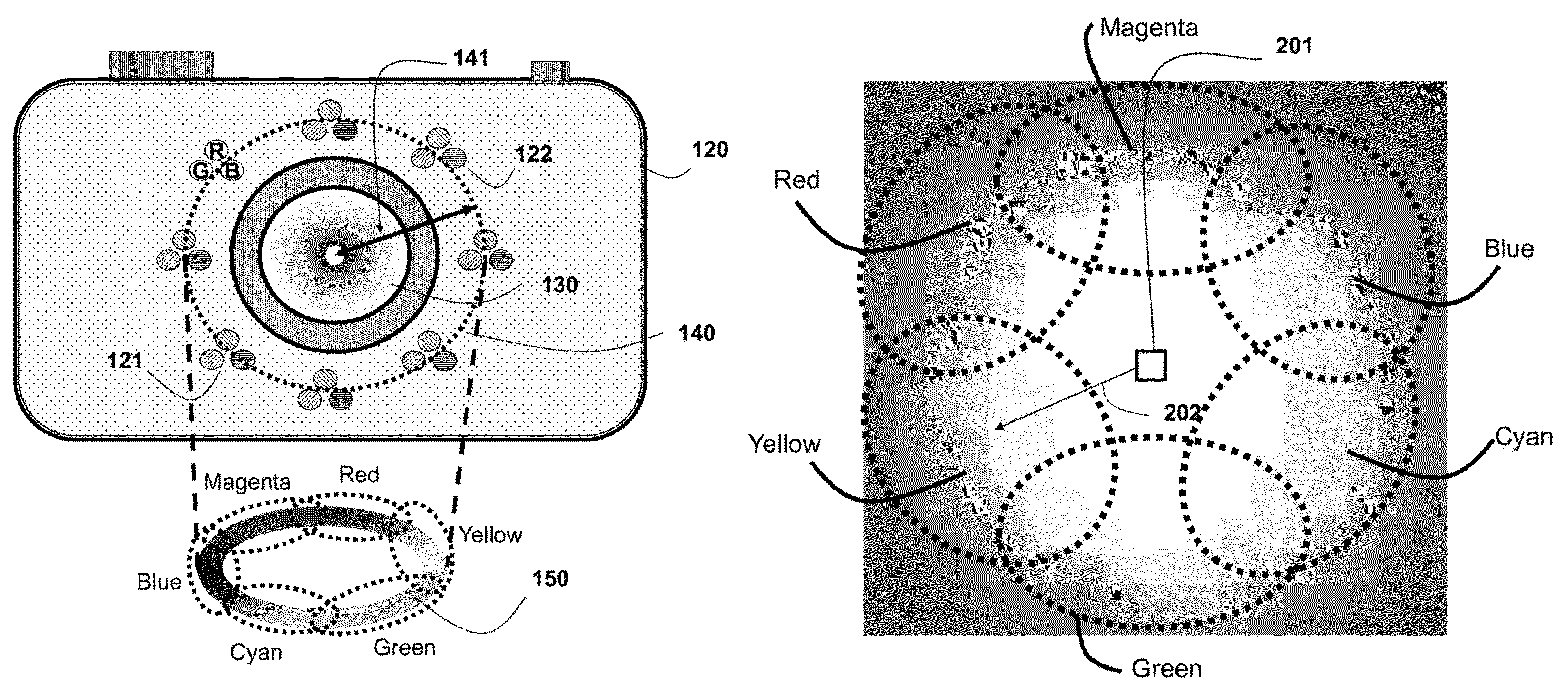
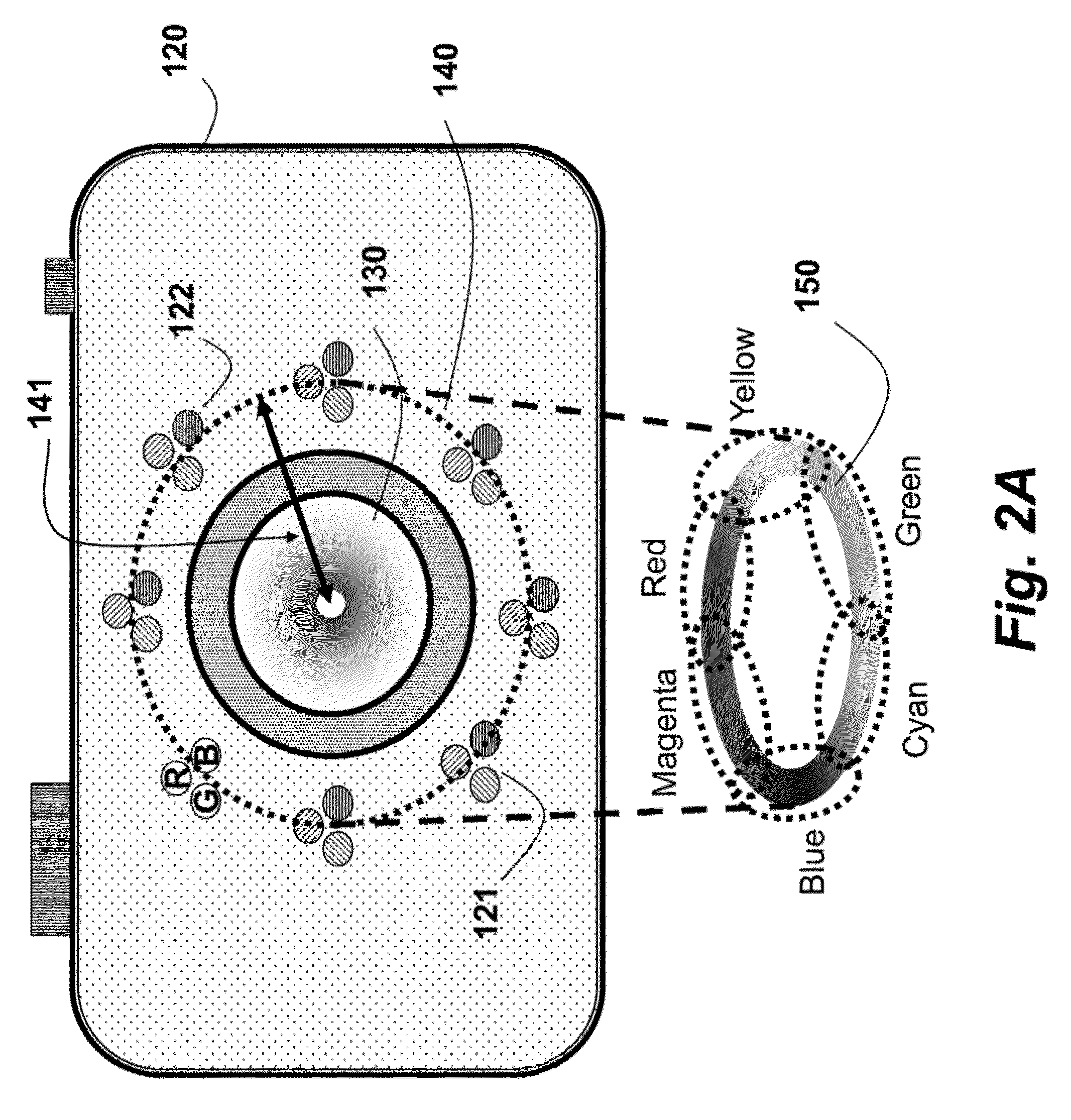
[0039]We use a 6-axis robot arm 110, on which a multi-flash camera (MFC) 120 is mounted. The MFC has multiple point lights arranged around the lens, and acquires images while illuminating the scene. A method determines a pose of each object to be picked by a gripper 111 using a set of images of each object. The method can be performed in a processor 210 connected to memory and input / output interfaces as known in the art.

[0040]Multi-Flas...


PUM


Abstract

A method and system extract features from an image acquired of an object with a specular surface by first acquiring an image while illuminating the object with a hue circle generated by a set of lights flashed simultaneously. The lights have different colors and are arranged circularly around a lens of a camera. Then, the features correspond to locations of pixels in the image within a neighborhood of pixels that includes a subset of the colors of the lights.

Description

RELATED APPLICATIONS[0001]This application is a continuation-in-part of U.S. application Ser. No. 13 / 549,791, “Method and Apparatus for Extracting Depth Edges from Images Acquired of Scenes by Cameras with Ring Flashes Forming Hue Circles,” filed by Assignee of the present application on Jul. 16, 2012 and incorporated herein by reference.FIELD OF THE INVENTION[0002]This invention relates generally to computer vision, and more particularly to extracting features from specular objects using active illumination.BACKGROUND OF THE INVENTION[0003]Advances in sensing technology and computer vision have enabled automation of many industrial tasks that require interaction with uncontrollable and dynamic environments. However, several problems persist with Objects that do not have a near-Lambertian reflectance. Specular objects with mirror-like transparent, or translucent surfaces possess material properties that are frequently considered as noise sources, and several methods attempt to suppr...

Claims


Application Information

Patent Timeline
16 Dec 2014
Publication
US8913825B2
IPC
G06K9/00; H04N5/225; G06T7/00
CPC
G06T7/0042; G06T2207/10024; G06T2207/30136; G06T7/0073; H04N5/2256; G06T7/73; G06T7/586; H04N23/56
Inventors
TAGUCHI, YUICHI; TUZEL, ONCEL