
Spindle for controlling wheel end endplay and preload

a spindle and preload technology, applied in the field of spindles, can solve the problems of increasing cost and time consumption, inhibiting the installation of a central tire inflation system, and difficult and time-consuming process for setting wheel end endplay and bearing preload

Active Publication Date: 2014-12-23
ARVINMERITOR TECH
View PDF13 Cites 24 Cited by
  • Summary
  • Abstract
  • Description
  • Claims
  • Application Information

AI Technical Summary

Benefits of technology

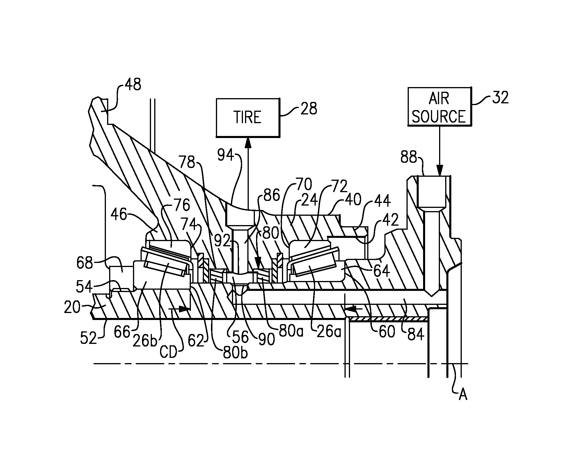
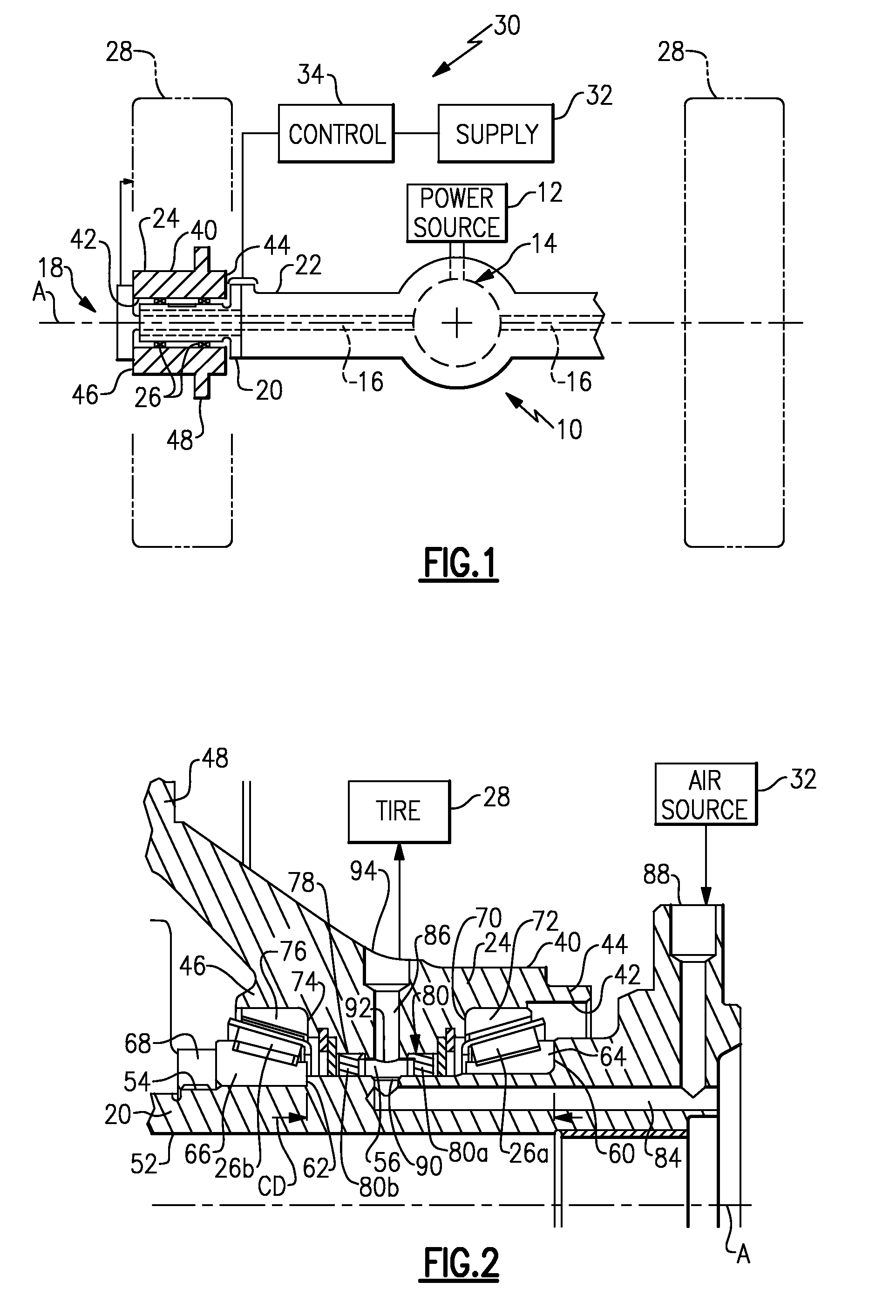
[0004]A spindle includes an inner bearing shoulder to seat an inner bearing and an outer bearing shoulder to seat an outer bearing. The inner and outer bearing shoulders are spaced apart by a controlled distance such that the outboard bearing is accurately positioned relative to the inboard bearing to control endplay and preload without requiring bearing adjustment.
[0005]In one example, a nut is tightened against the outboard bearing such that the outboard bearing comes into contact with the outboard bearing shoulder to prevent excessive preload. Further, the nut does not need to be subsequently backed-off to ensure acceptable endplay because a desired endplay and preload is already provided by the controlled distance between the inboard and outboard bearing shoulders.

Problems solved by technology

The process for setting wheel end endplay and bearing preload is difficult and time consuming.
This approach has proven to be effective in controlling the endplay; however, the installation of an additional component, i.e. the spacer, increases cost and continues to be time consuming.
Another disadvantage with this type of approach is that the spacer inhibits the installation of a central tire inflation system (CTIS).

Method used


Image

  • Spindle for controlling wheel end endplay and preload
  • Spindle for controlling wheel end endplay and preload

Examples


Embodiment Construction

[0010]FIG. 1 shows a drive axle 10 receiving driving input from a power source 12, such as an engine or electric motor for example. The driving input drives an input gear assembly 14 that includes a differential mechanism as known. The gear assembly 14 drives axle shafts 16 that are coupled to drive wheel end assemblies 18. One example of a wheel end assembly 18 is shown to the left of FIG. 1. It should be understood that the opposite wheel end assembly 18 would be similarly configured.

[0011]The wheel end assembly 18 includes a non-rotating spindle 20 that is mounted to an axle housing 22 or other non-rotating axle structure. The axle housing 22 houses the gear assembly 14 and axle shafts 16. A wheel hub 24 is rotatably supported on the spindle 20 by bearings 26. In one example, the bearings 26 comprise half-stand bearings (with reduced tolerance); however, other types of bearings could also be used. A tire 28 and associated rim are mounted for rotation with the wheel hub 24 about a...


PUM

PropertyMeasurementUnit
distanceaaaaaaaaaa
diameteraaaaaaaaaa
timeaaaaaaaaaa

Abstract

A spindle includes an inner bearing shoulder to seat an inner bearing and an outer bearing shoulder to seat an outer bearing. The inner and outer bearing shoulders are spaced apart by a controlled distance such that the outboard bearing is accurately positioned relative to the inboard bearing to control endplay and preload without requiring bearing adjustment.

Description

TECHNICAL FIELD[0001]The subject invention relates to a spindle supported on a hub for an axle that is configured to control wheel end endplay and preload without the need for bearing adjustment or additional components.BACKGROUND OF THE INVENTION[0002]A wheel end includes inboard and outboard bearings that are used to rotatably support a wheel hub for rotation relative to a spindle. The process for setting wheel end endplay and bearing preload is difficult and time consuming. One typical process utilizes a precision machined spacer that is positioned between bearing cones of the inboard and outboard bearings in an attempt to accurately control the endplay. This approach has proven to be effective in controlling the endplay; however, the installation of an additional component, i.e. the spacer, increases cost and continues to be time consuming.[0003]Another disadvantage with this type of approach is that the spacer inhibits the installation of a central tire inflation system (CTIS)....

Claims


Application Information

Patent Timeline
Patent Type & Authority Patents(United States)
IPC IPC(8): B60C23/00B60C23/10
CPCB60C23/003Y10T29/49963B60C23/00318B60C23/00345B60C23/00363
Inventor ESCHENBURG, DALEGONSKA, DAVID
Owner ARVINMERITOR TECH
Learn More