Dual-clutch transmission

a transmission and dual-clutch technology, applied in the direction of clutches, fluid-actuated clutches, mechanical equipment, etc., can solve the problems of not being necessary or even useful, and the gear selector cannot be used anymor

Active Publication Date: 2014-12-23
AUDI AG
View PDF13 Cites 3 Cited by
  • Summary
  • Abstract
  • Description
  • Claims
  • Application Information

AI Technical Summary

Benefits of technology

[0013]This has the significant advantage that at least a partial function of the dual-clutch transmission is automatically deactivated when the parking lock is engaged, resulting in potential energy savings, while at the same time increasing the safety of the clutch transmission. At least one of the pressure control valves arranged upstream of the clutches and / or of the gear selectors is connected downstream of the switching device, wherein the switching device is also connected with the parking lock.
[0014]According to an advantageous feature of the present invention, the parking lock and the corresponding pressure control valve may be connected to the same connection of the switching device or may have a common supply line arranged downstream of the switching device. The parking lock is released or disengaged by applying pressure from the hydraulic medium. In this way, the at least one pressure control valve is also switched unpressurized and the function thus set is deactivated when the parking lock is engaged. For example, when the pressure control valve is arranged upstream of the gear selectors, the hydraulic medium is no longer supplied to the switching mechanism of the transmission when the parking lock is engaged, so that a gear can no longer be set with the gear selector. However, this is also not necessary or even useful when the parking lock is engaged. As a result, energy can be saved by actuating the parking lock because the hydraulic medium needs no longer be supplied to the gear selectors, so that the capacity of the pressure source, in particular of a pump pressurizing the hydraulic medium, can be reduced.
[0016]According to an advantageous feature of the present invention, the switching device may have at least one first switching valve which is connected with the pressure control valve at a first connection, at a second connection with the pressure source and at a third connection with the tank. The switching valve may advantageously be constructed as a 3 / 2-way switching valve which can assume two extreme positions or extreme states. Advantageously, the switching valve connects in a first extreme state the parking lock and the corresponding pressure control valve with the tank, so that both can be switched unpressurized, and connects in a second extreme state the parking lock and the corresponding pressure control valve with the pressure source, so that the parking lock is disengaged and pressurized hydraulic medium is supplied to the pressure control valve.
[0021]According to an advantageous feature of the present invention, the pressure source may be in form of at least one pump which can advantageously be driven by an electric motor, so that the pump capacity is independent of the rotation speed of a combustion engine that can be operatively connected to the clutch transmission. When both first pressure control valves associated with the clutches are connected with the switching device or the switching valve, at least the clutches are switched unpressurized when the parking lock is actuated, thereby preventing force transmission from the combustion engine to the transmission, while still allowing gear actuation processes to be carried out in the transmission.
[0022]According to another advantageous feature of the present invention, at least the (first or second) switching valve connected with the parking lock may have, in addition or alternatively to the return spring, at least one valve face which is connected with the pressure source for pressure regulation. The corresponding switching valve is hereby constructed such that, when the pressure of the pressure source exceeds a predetermined value, the switching valve moves into its extreme state in which the parking lock is connected with the tank. For example, the parking lock can hereby be protected from exceedingly high pressures.
[0024]According to another advantageous feature of the present invention, at least the switching valve connected with the parking lock may connect the pressure source, in particular the pressure accumulator, with the tank, even when the parking lock is connected with the tank. In this way, the pressure accumulator is emptied when the parking lock is engaged, thereby preventing the parking lock from unintentionally disengaging.

Problems solved by technology

For example, when the pressure control valve is arranged upstream of the gear selectors, the hydraulic medium is no longer supplied to the switching mechanism of the transmission when the parking lock is engaged, so that a gear can no longer be set with the gear selector.
However, this is also not necessary or even useful when the parking lock is engaged.

Method used


Image

  • Dual-clutch transmission
  • Dual-clutch transmission
  • Dual-clutch transmission

Examples


Embodiment Construction

[0032]Throughout all the figures, same or corresponding elements may generally be indicated by same reference numerals. These depicted embodiments are to be understood as illustrative of the invention and not as limiting in any way. It should also be understood that the figures are not necessarily to scale and that the embodiments are sometimes illustrated by graphic symbols, phantom lines, diagrammatic representations and fragmentary views. In certain instances, details which are not necessary for an understanding of the present invention or which render other details difficult to perceive may have been omitted.

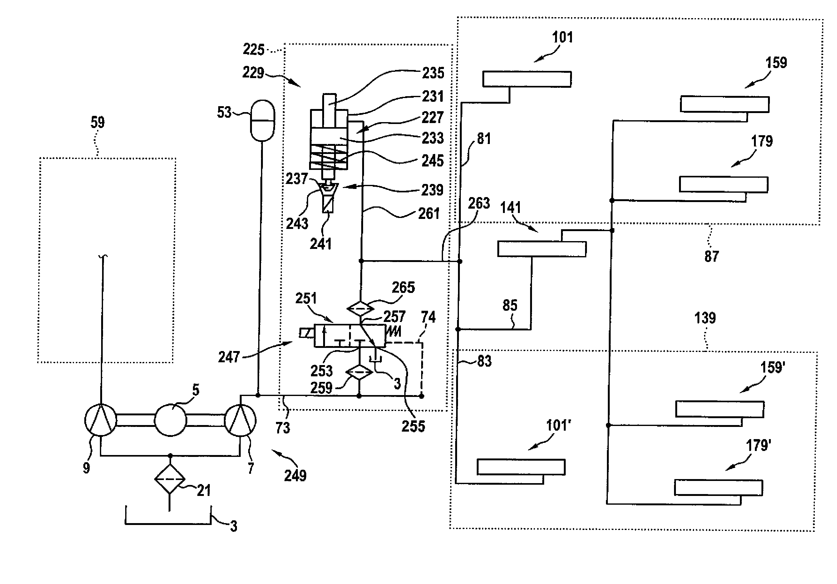
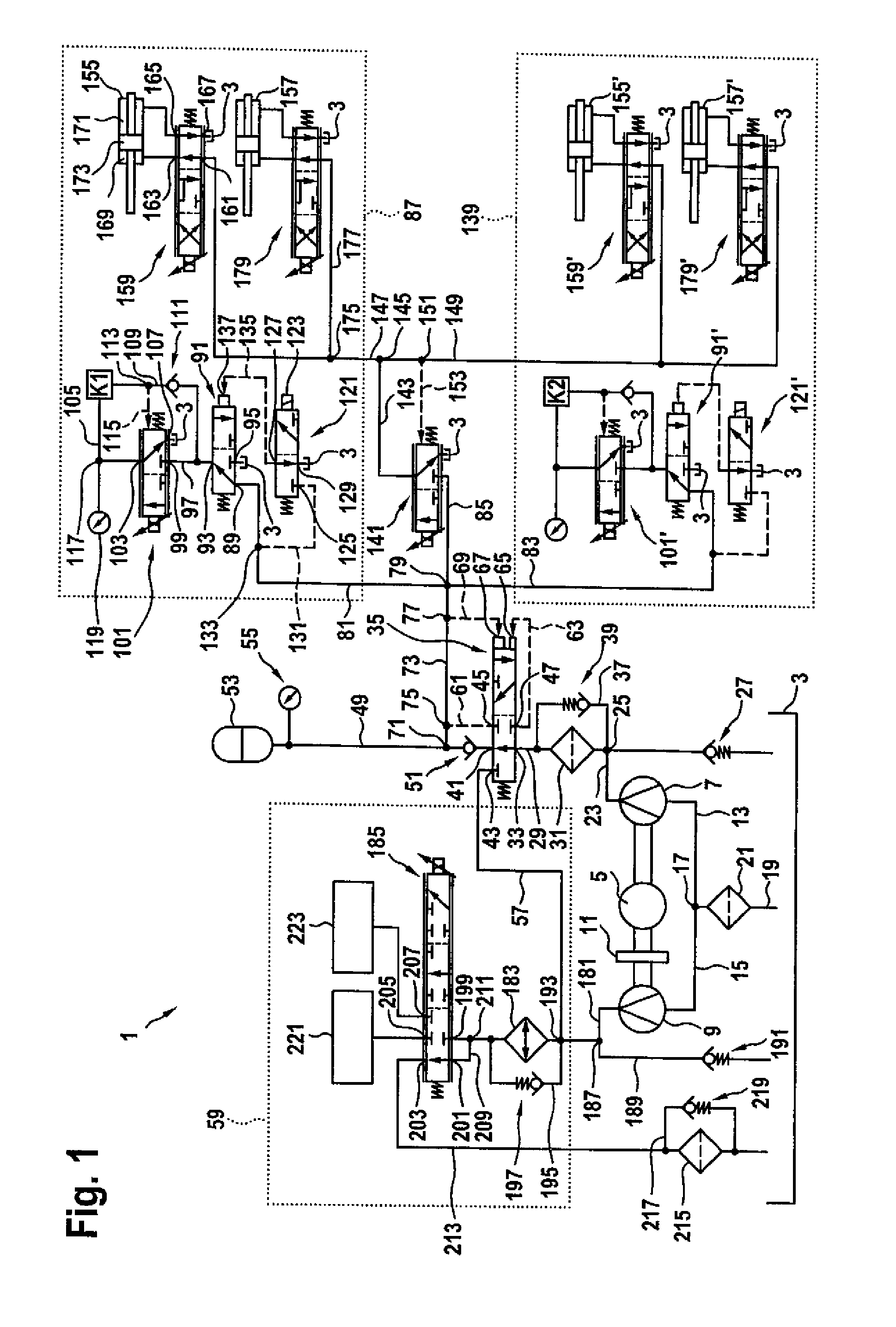
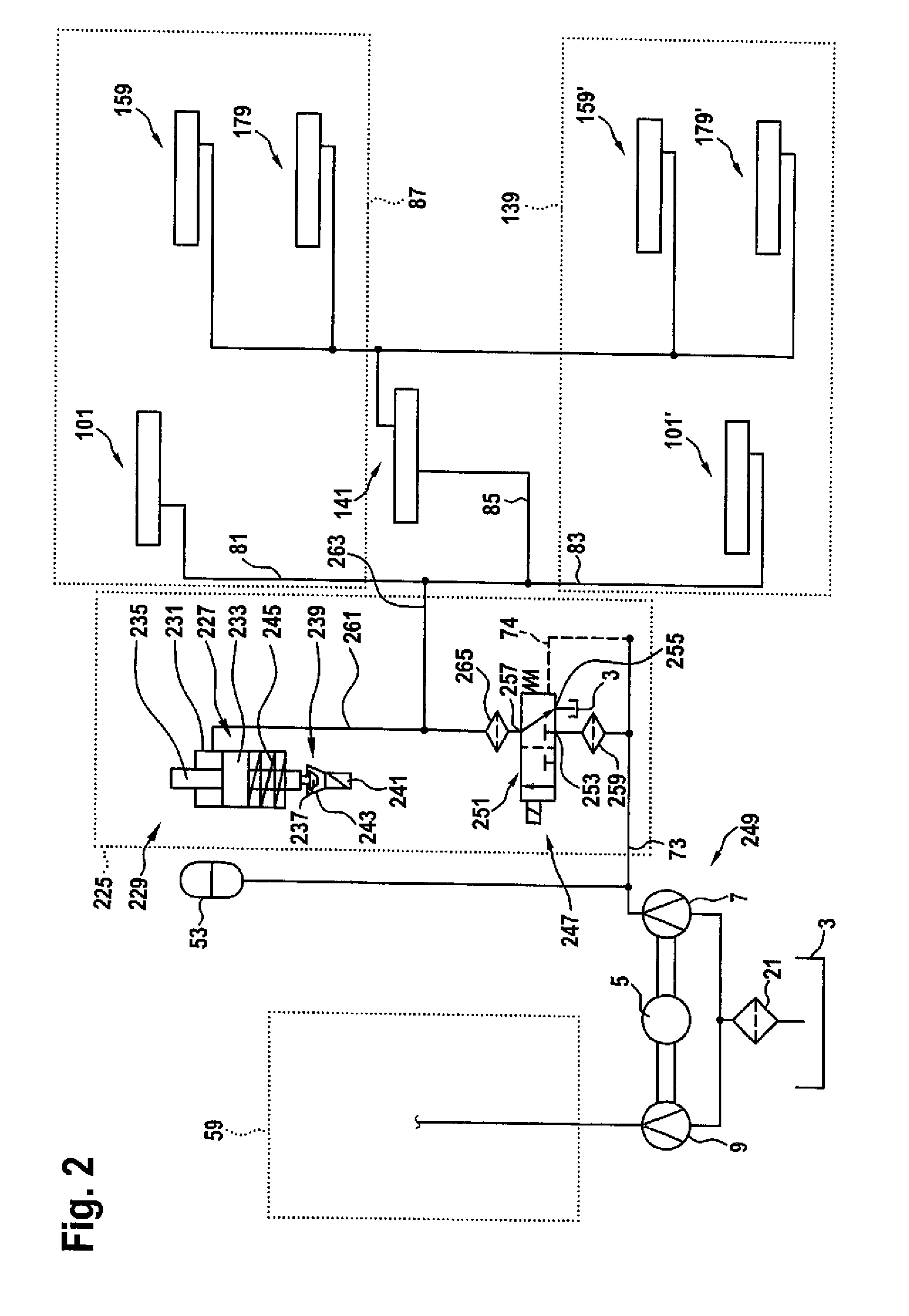
[0033]Turning now to the drawing, and in particular to FIG. 1, there is shown a hydraulic circuit 1 for actuating, in particular operating, a clutch and for engaging and disengaging gears of a dual-clutch transmission as well as for cooling a dual-clutch transmission. The hydraulic circuit 1 includes a tank 3 used, in particular, as reservoir or sump for a hydraulic medium u...


PUM


Abstract

A clutch transmission, in particular a dual-clutch transmission for a vehicle, such as a motor vehicle, includes at least one automatic transmission with a hydraulically actuatable clutch and at least one hydraulically actuatable gear actuator, and a hydraulic circuit having a tank supplying an unpressurized hydraulic medium and a pressure source supplying a pressurized hydraulic medium. For operating the respective clutch, a first pressure control valve and at least one second pressure control valve are arranged upstream of the respective coupling. At least one of the pressure control valves is connected with an upstream switching device which connects the at least one pressure control valve and a hydraulically actuatable parking lock either with the pressure source or with the tank.

Description

CROSS-REFERENCES TO RELATED APPLICATIONS[0001]This application claims the priority of German Patent Application Serial No. 10 2011 100 857.1, filed May 6, 2011, pursuant to 35 U.S.C. 119(a)-(d), the content of which is incorporated herein by reference in its entirety as if fully set forth herein.BACKGROUND OF THE INVENTION[0002]The present invention relates to a clutch transmission, in particular a dual-clutch transmission for a vehicle, in particular a motor vehicle.[0003]The following discussion of related art is provided to assist the reader in understanding the advantages of the invention, and is not to be construed as an admission that this related art is prior art to this invention.[0004]Dual-clutch transmissions are preferably used in passenger automobiles. A dual-clutch transmission usually includes two coaxially arranged gear input shafts which are each associated with a respective transmission, to be referred here also as subsidiary transmissions. A corresponding clutch is...

Claims


Application Information

Patent Timeline
Patent Type & Authority Patents(United States)
IPC IPC(8): F16D48/02F16H61/22F16H61/00F16H61/688F16H61/02F16H63/34
CPCF16H61/0206F16D48/0206F16D2048/029F16H63/3483F16D25/14F16D2048/0293F16H61/688F16D2048/0242F16D2048/0281F16H61/0021
Inventor SCHULLER, DIETMARBAUER, MARTIN
Owner AUDI AG
Why Eureka
Try Eureka