Device for opening an ampoule

a technology for ampoules and ampoules, which is applied in the field of ampoules for opening devices, can solve the problems of large amount of force required to break ampoules, complex devices in design and correspondingly expensive manufacture, and large space requirements of devices, so as to increase the flexibility of devices

Inactive Publication Date: 2014-12-23
MEDMIX SYST
View PDF19 Cites 11 Cited by
  • Summary
  • Abstract
  • Description
  • Claims
  • Application Information

AI Technical Summary

Benefits of technology

[0009]It is an object of the present invention to set out a device for opening an ampoule in which the force used to break open the ampoule is minimised. The device should also be easy to use and should be designed as simply and compactly as possible.
[0014]In such a design of the device the rotary force produced by the user is converted into a radial shearing force acting perpendicularly to the longitudinal axis of the ampoule. The shearing force also acts optimally from the side on the ampoule head, i.e. from a direction perpendicular to the longitudinal axis of the ampoule. More particularly, in a preferred embodiment it is possible to position the break-off section in such a way relative to the ampoule head that the shearing force acts on the ampoule head as far as possible from the predetermined breaking point. This achieves a lever effect, which reduces the force required for breaking off the ampoule head. The force for breaking open the ampule is minimised through this design of the device.
[0023]In a preferred embodiment the rotary element has a fragmentation section which is flexibly designed in the radial direction and / or is pivotably arranged on the proximal section of the rotary element in the radial direction, and to which the break-off section is adjoined in the distal direction. The rotary element can then preferably be rotated further relative to the housing in the direction of operation from the intermediate position into an end position, wherein in the area of the side wall the housing has a second guiding structure, which is designed so that during rotation from the intermediate position into the end position it presses the fragmentation section radially inwards so that the ampoule head of an ampoule accommodated in the interior is fragmented after having been broken off. In this embodiment the ampoule is thus opened in such a way that the ampoule head is first broken off from the ampoule body and then fragmented. Compared with direct fragmentation of an ampoule head, which has not been broken off from the ampoule body beforehand, the maximum force exerted when opening an ampoule in this manner is essentially minimised as the external forces acting on the ampoule head are not absorbable by the ampoule body through internal force equalisation. Fragmenting prevents liquid residues of the fluid product remaining in the ampoule head. Preferably the breaking off and subsequent fragmentation of the ampoule head take place in a single procedure, for example through a continuous rotary movement of the rotary element relative to the housing. The range of rotation of the rotary element relative to the housing is preferably limited, and the angular range of this limited range of rotation is preferably approximately 180°.
[0025]The rotary element advantageously has a sleeve-like section which is arranged proximally adjacent to the fragmentation section and which has several longitudinal slits arranged opposite to one another in the radial direction. The sleeve-like section can, in particular, serve to hold the ampoule body in position when the ampoule head is broken off. The longitudinal slits are intended to increase the flexibility of the rotary element and, more particularly, to facilitate the pressing together of the possibly present opposite elements of the fragmentation section.
[0028]Preferably the fragmentation section thickens radially in a circumferential direction contrary to the actuating direction. On rotating the rotating element relative to the housing from the intermediate position into the end position the fragmentation section is thereby increasingly pressed radially inwards towards the longitudinal axis, as a result of which the external force acting on the ampoule head is increased. To increase its flexibility the fragmentation section can have longitudinal grooves on its radial outer side. The break-off section can also have longitudinal grooves on its radial outer side.

Problems solved by technology

As the ampules are arranged eccentrically with regard to the axis of rotation these devices require a relatively large amount of space.
However, the device is complex in design and correspondingly costly to manufacture.
These devices have the drawback that a relatively large amount of force is required to break the ampoule.

Method used


Image

  • Device for opening an ampoule
  • Device for opening an ampoule
  • Device for opening an ampoule

Examples


Embodiment Construction

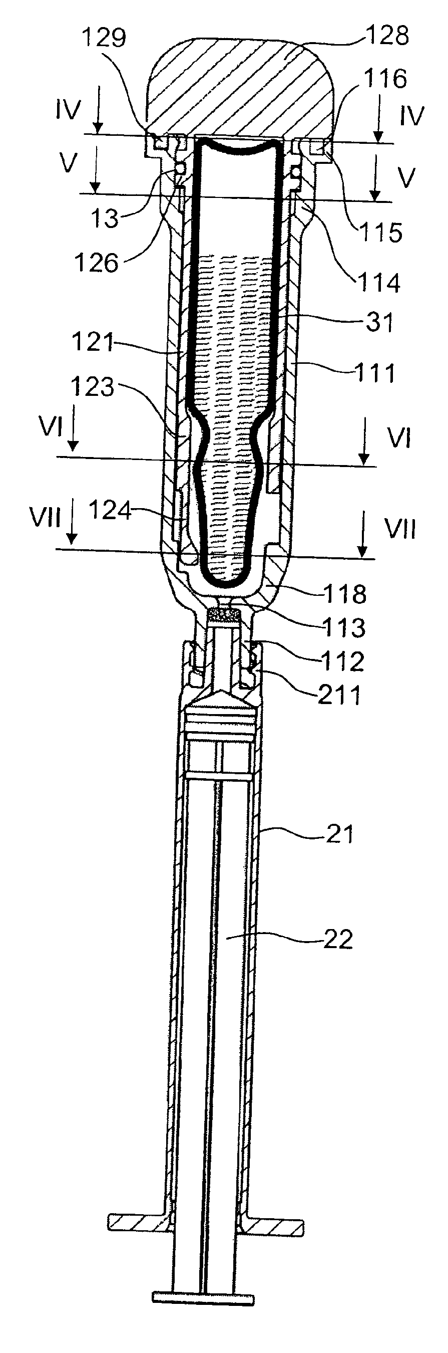
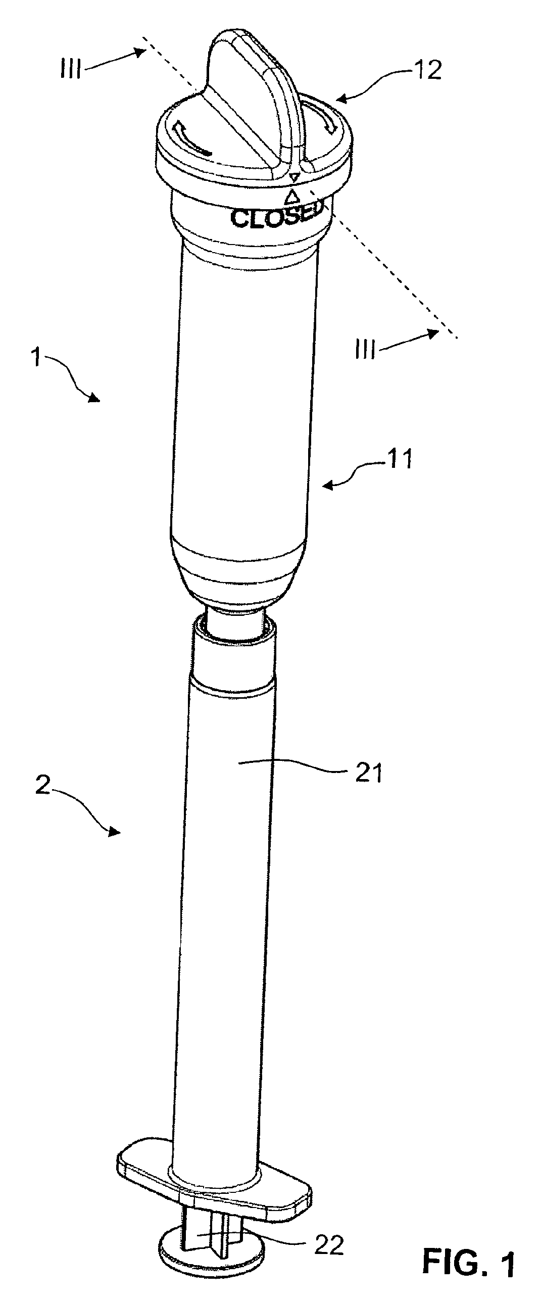
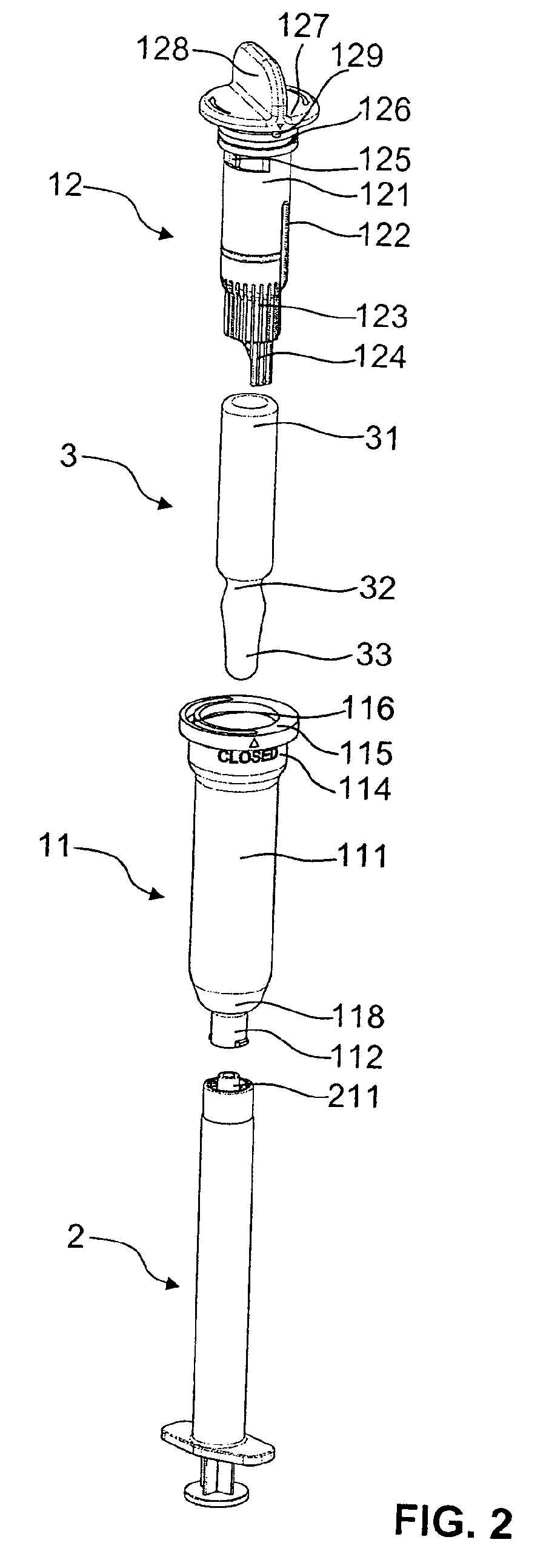
[0047]FIGS. 1 to 16 show a first embodiment of an opening device in accordance with the invention. The opening device 1, which comprises a housing 11 and a rotary element 12 inserted into the housing 11, is intended for opening an ampoule 3 and is here connected to a syringe 2. To open the ampoule 3 the rotary element 12 can be rotated relative to the housing 11 in an actuating direction. In the following the actuating direction is always the circumferential direction in which the rotary element 12 is rotated relative to the stationary housing 11 in order to open the ampoule 3. The distal direction of the opening device 1 extends from a proximal insert opening of the housing 11 to a distal outlet opening 113 and corresponds with the direction in which the ampoule 3 can be inserted with the ampoule head 33 first into the opening device 1. The proximal direction is the direction contrary to the distal direction.

[0048]The ampoule 3, which can be seen more particularly in FIG. 2, is an ...


PUM


Abstract

A device for opening an ampoule (3) comprises a hollow cylindrical housing (11) having an interior for accommodating the ampoule (3) and a rotary element (12) having a proximal section (121), to which a break-off section (124) extending in a distal direction is connected to. The break-off section (124) is flexible in a radial direction and is pivotably connected to the proximal section (121) in the radial direction. The rotary element (12) is rotatable relative to the housing (11) about the longitudinal axis. The housing (11) has a first guiding structure (119) for pressing the break-off section (124) inward during a rotation of the rotary element so that the break-off section (124) exerts a radial shear force on an ampoule head (33) of an ampoule (3) to break the ampoule head (33) off of the ampoule body (31).

Description

CROSS REFERENCE TO RELATED APPLICATIONS[0001]This application is a National Stage of International Application No. PCT / CH2011 / 000047 filed Mar. 10, 2011, claiming priority based on Swiss Patent Application No. 00507 / 10 filed Apr. 8, 2010, the contents of all of which are incorporated herein by reference in their entirety.TECHNICAL FIELD[0002]The present invention relates to a device for opening an ampoule. The device comprises a housing for accommodating an ampoule and is designed to break the ampoule head off from the ampoule body.PRIOR ART[0003]Ampoules are often used, particularly in medicine and chemistry, to store fluid products, for example medicinal products or aggressive substances such as monomers in a sterile manner and protected against diffusion. Conventional ampoules are generally made of glass and have an interior, which is entirely closed off with regard to the exterior, in which the fluid product is stored. Such ampoules are usually elongated and have an ampoule head...

Claims


Application Information

Patent Timeline
Patent Type & Authority Patents(United States)
IPC IPC(8): B67B7/92
CPCB67B7/92Y10T225/30Y10T225/329Y10T225/371
Inventor KAYSER, RALPH, EGON
Owner MEDMIX SYST
Why Eureka
Try Eureka