LED module packaging structure with an IC chip

a technology of led modules and packaging structures, applied in the direction of basic electric elements, electrical equipment, semiconductor devices, etc., can solve the problems of easy damage to the operation of the ic chip, difficulty in transmitting the operating power and control signal to the led module from the central control, and inability to display, etc., to achieve the effect of improving the led module packaging structure and long transmission of the central control

Inactive Publication Date: 2014-12-23
UBLEDS
View PDF3 Cites 1 Cited by
  • Summary
  • Abstract
  • Description
  • Claims
  • Application Information

AI Technical Summary

Benefits of technology

[0007]It is an object of the present invention to provide an improved LED module packaging structure with an IC chip being a LED module which is formed by arranging a packaging groove on a carrier stand, injecting a transparent gel into the packaging groove, and packaging more than one LED chip and an IC chip in the packaging groove. Each LED chip and the IC chip are packaged in the packaging groove and integrated by a conductive integrating lamination. Around a side of the integrating lamination, a power input end, a power output end, at least one data signal input end, and at least one data signal output end are extended from an inside of the packaging groove to an outside of the carrier stand. One terminal of each LED chip is electrically connected to a controlling port of the IC chip. The other terminal of each LED chip is electrically connected to the power input end. The power input end is further connected to a zener diode for allowing a power input port of the IC chip to acquire an operating power from the zener diode. The power output end is electrically connected to the integrating lamination, and the integrating lamination is electrically connected to a power output port of the IC chip. At least one signal input port and at least one signal output port of the IC chip are electrically connected to the data signal input end and the data signal output end, respectively. The LED module applied to a full-color or self-color illuminant of central control utilizes the zener diode connected to the power input end within the packaging groove of the carrier stand to lower or modulate a voltage of an external power. While the IC chip receives a data signal from the data signal input end, the IC chip receives a matched operating voltage via the zener diode to drive the LED chip to shine, thereby attaining the long transmission of the central control easily.
[0009]It is a further object of the present invention to provide an improved LED module packaging structure with an IC chip. The power input end is connected to a one-way zener diode which is connected to the power input port of the IC chip in series. The one-way zener diode lowers the voltage of the external power, so that the IC chip receives the matched operating voltage from the one-way zener diode for operating. A diode is further in a series connection between the power input end and the one-way zener diode, so that the diode generates a protective effect for the IC chip when the external power is reversely connected. Furthermore, a second two-way zener diode is in a series connection between the power input end and the integrating lamination, so that the IC chip and the LED chip integrated on the integrating lamination generate a positive and negative static electricity and a surge protection via the second two-way zener diode.
[0010]It is a further object of the present invention to provide an improved LED module packaging structure with an IC chip. The power input end is serially connected to a one-way zener diode, which is connected to the IC chip in parallel, via a resistance for forming a constant voltage circuit. The constant voltage circuit lowers and stabilizes the voltage of the external power, so that the IC chip receives the matched operating voltage from the serially connected one-way zener diode and the resistance for operating, and renders the IC chip and the LED chip provided with surge and static electricity protections.

Problems solved by technology

Although the conventional technique of LED display screen is completed, the limiting resistance and the driving unit need to be added onto the circuit boards, which may cause the distance between the adjacent full-colored LED to be too large, so that a more exquisite image is unable to be displayed.
Although this prior art improves the RFI and EMI problems and makes the displayed images more exquisite, it still has difficulty in transmitting the operating power and the control signal to the LED module from the central control.
If the voltage of the external power of the LED module is higher than the operating voltage of the IC chip, the operation of the IC chip is easily affected and may be damaged.
Although the IC chip can receive the normal operating voltage by disposing an IC chip with constant voltage on the external power, the process of the circuit board or the using scheme of the electrical elements is not simplified.

Method used


Image

  • LED module packaging structure with an IC chip
  • LED module packaging structure with an IC chip
  • LED module packaging structure with an IC chip

Examples


Embodiment Construction

[0020]Before describing in detail, it should note that the like elements are denoted by the similar reference numerals throughout disclosure.

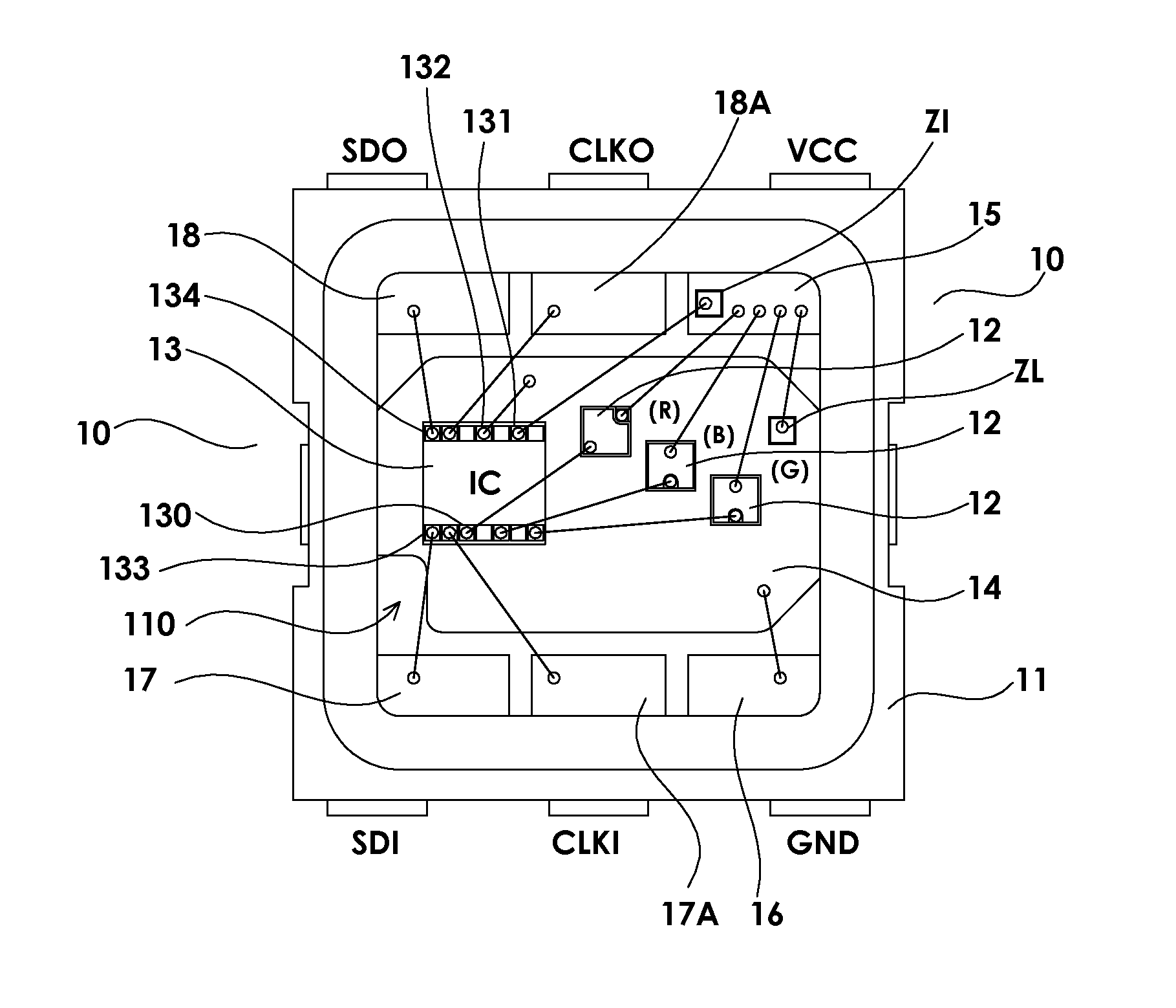
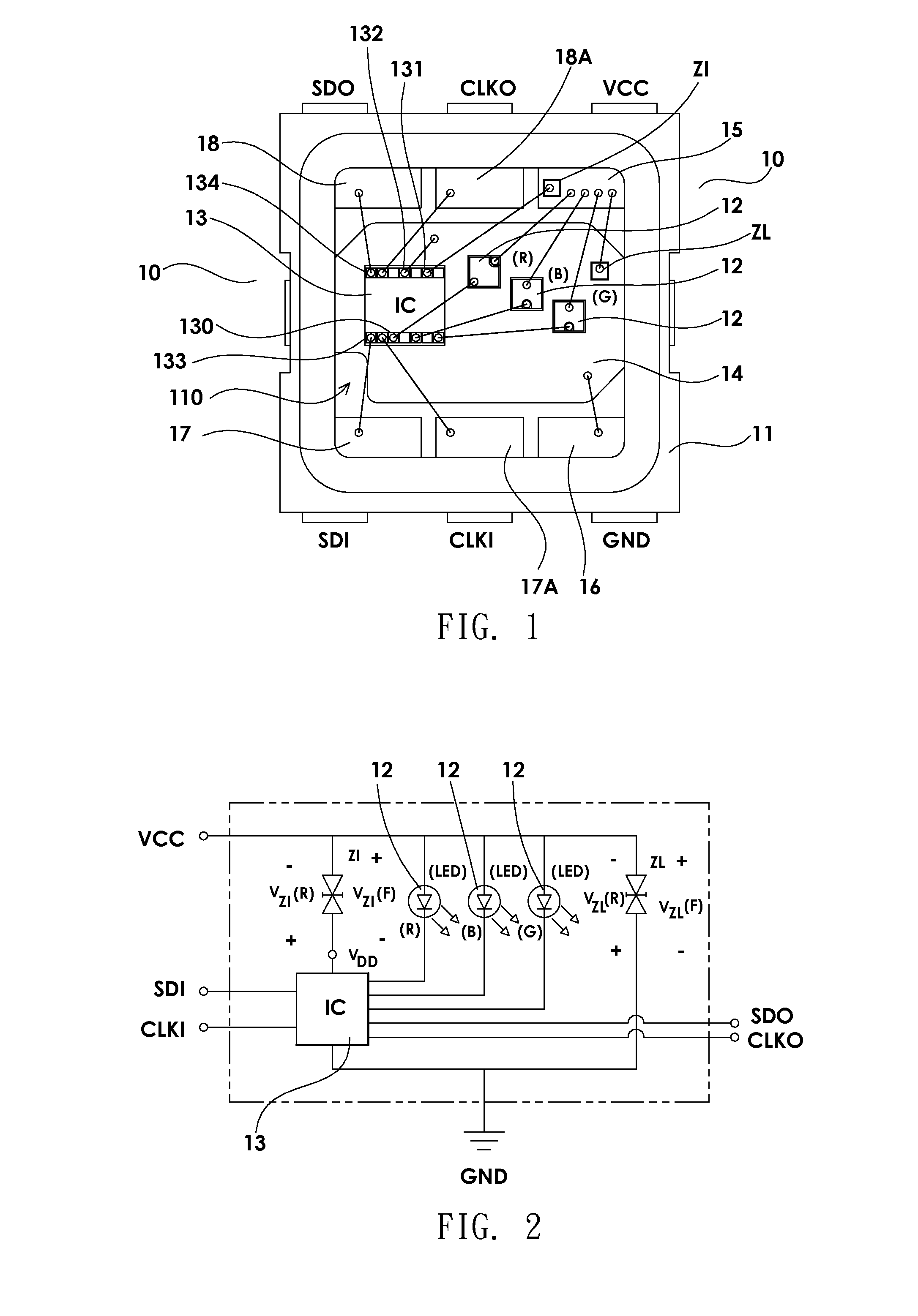
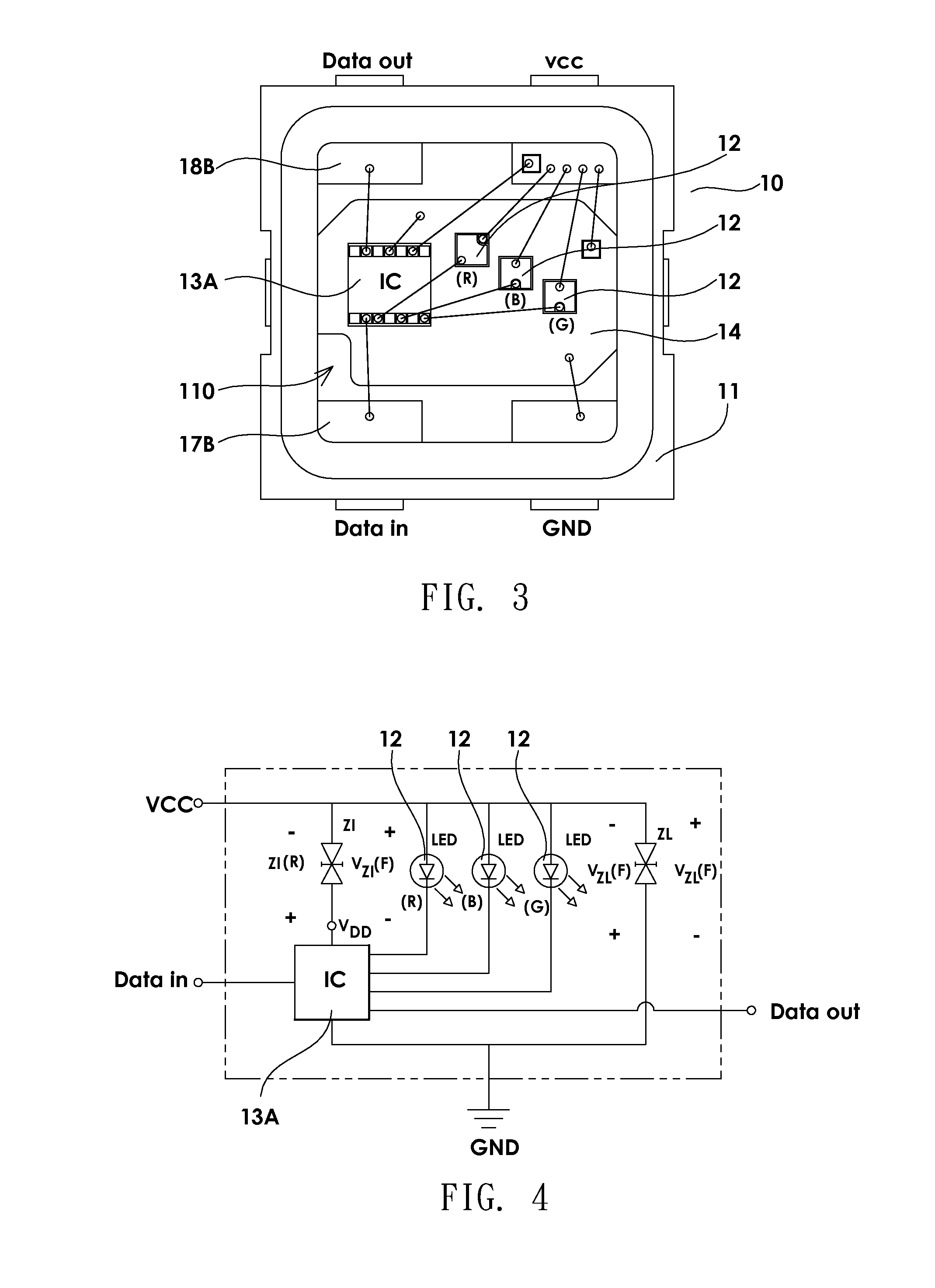
[0021]The present invention provides an improved LED module packaging structure with an IC chip. Referring to FIGS. 1 and 2, a LED module 10 is formed by arranging a packaging groove 110 on a carrier stand 11, injecting a transparent gel (not shown) into the packaging groove 110, and packaging more than one LED chip 12 (the red, green, and blue chips), which can be red, green, and blue chips, and an IC chip 13 in the packaging groove 110. Each LED chip 12 (the red, green, and blue chips), namely the red, green, and blue chips and the IC chip 13 are packaged in the packaging groove 110 and integrated by a conductive integrating lamination 14. Around a side of the integrating lamination, a power input end 15, a power output end 16, at least one data signal input end 17, and at least one data signal output end 18 are extended from an inside of the...


PUM


Abstract

An improved LED module packaging structure with an IC chip includes a power input end in a packaging groove of a carrier stand connected to a zener diode and a power input port of the IC chip acquiring an operating power from the zener diode, so that the LED module applied to a full-color or self-color illuminant of central control utilizes the zener diode connected to the power input end within the packaging groove of the carrier stand to lower or modulate the voltage of an external power. While the IC chip receives a data signal from the data signal input end, the IC chip receives a matched operating voltage via the zener diode to drive the LED chip to shine, thereby attaining a long transmission of the central control easily.

Description

BACKGROUND OF THE INVENTION[0001]1. Field of the Invention[0002]The present invention relates to a LED module packaging structure controlled by a central signal for transmitting in long distance, in particular to an improved LED module packaging structure with an IC chip.[0003]2. Description of the Related Art[0004]Applications of a Light Emitting Diode (LED) can be divided into the functions of displaying and lightening. Except for the self-colored LED which has been popularly used in lightening, the multi-colored and the full-colored LED fulfills the visual demand on displaying. To display various colors of lights, each full-colored LED packaging structure includes at least red (R) LED chips, green (G) LED chips, and blue (B) LED chips, thereby mixing the RGB colors for various colors of lights. Because the percentage of the RGB colors that the colors of lights require are different, the full-colored LED needs to be matched to a driving unit for precisely controlling the mix light...

Claims


Application Information

Patent Timeline
Patent Type & Authority Patents(United States)
IPC IPC(8): H01L33/48H01L33/00H01L27/15
CPCH01L2224/48137H01L2924/0002H01L25/167H01L33/48H01L2224/48247H01L27/15H01L2224/48257
Inventor HSUE, SHOUWEN
Owner UBLEDS
Why Eureka
Try Eureka