Tear resistant paperboard structure and method

a technology of laminate sheets and structures, applied in the field of laminate sheets, can solve the problems of low tear resistance and burst resistance, unsatisfactory texture, and undesirable texture, and achieve the effects of improving the dimensional stability, reducing the amount of material, and improving the packaging structur

Inactive Publication Date: 2015-05-21
HOLLAND BLAIR
View PDF0 Cites 0 Cited by
  • Summary
  • Abstract
  • Description
  • Claims
  • Application Information

AI Technical Summary

Benefits of technology

[0017]It is another object of the present invention to provide a tear resistant paperboard packaging laminate that can be produced at a fraction of the cost of packaging laminates utilizing cross-directionally oriented films.
[0018]It is another object of the present invention to provide a paperboard packaging laminate with improved dimensional stability, and the ability to stay flat under varying environmental conditions.
[0019]It is another object of the present invention to provide a paperboard packaging laminate which provides double-sided printability with a minimum amount of material.
[0020]It is another object of the present invention to provide a laminated paperboard laminate for an improved packaging structure.
[0021]It is another object of the present invention to provide a laminated paperboard substrate for packaging that is child-resistant, yet easily opened by the intended consumer.
[0022]It is yet another object of the invention to provide a laminated paperboard substrate for packaging wherein the strength needed to open the package can be controlled.

Problems solved by technology

Moreover, conventional packaging materials, such as for packaging unit dose pharmaceuticals, lack high tear-resistance and burst-resistance, which are desirable characteristics for various packaging applications including pharmaceutical packaging.
Moreover, it is commonly known that packaging for pharmaceutical products must be accessible by a person using the medication, but also child-resistant.
This presents a number of drawbacks, particularly when the recipient of the medication is lacking manual dexterity or strength.
This texture is undesirable, namely in packaging such as the ones described above, where an inner sliding component (or “insert”) is provided.
Indeed, the stickiness of the film hinders the sliding motion of the insert, or of other movable parts in the packaging.
Therefore, if print is desired to appear on two sides of a substantially flat component of the packaging, the laminate material must be folded, which is results in a bulkier component and requires more of the laminate material.
Moreover, the film side is not readily adherable.
Therefore special adhesive substances and / or processes are required to adhere a component to the film side of the packaging, which results in increased manufacturing costs, etc.
Furthermore, such conventional packaging material will tend to warp under certain conditions, such as high levels of humidity, etc., due to the asymmetry of the composition.
This warping effect challenges the manufacturing of packages made with such materials and / or results in undesirable deformations in the final packages.
Moreover, despite advances in multi-layer film technology, the use of such films as the strength layer in a laminated structure with paperboard is still characterized by relatively poor tear characteristics.
The poor tear characteristics of the paperboard are imparted to the cross-laminated layers and the tear propagates through each of the layers.
Also, in fabricating products, the dissimilar materials of such laminates can present a number of problems including poor adhesion of the film to the paperboard surface, which can result in delaminating and other undesirable characteristics in the finished laminated product.

Method used


Image

  • Tear resistant paperboard structure and method
  • Tear resistant paperboard structure and method
  • Tear resistant paperboard structure and method

Examples


Embodiment Construction

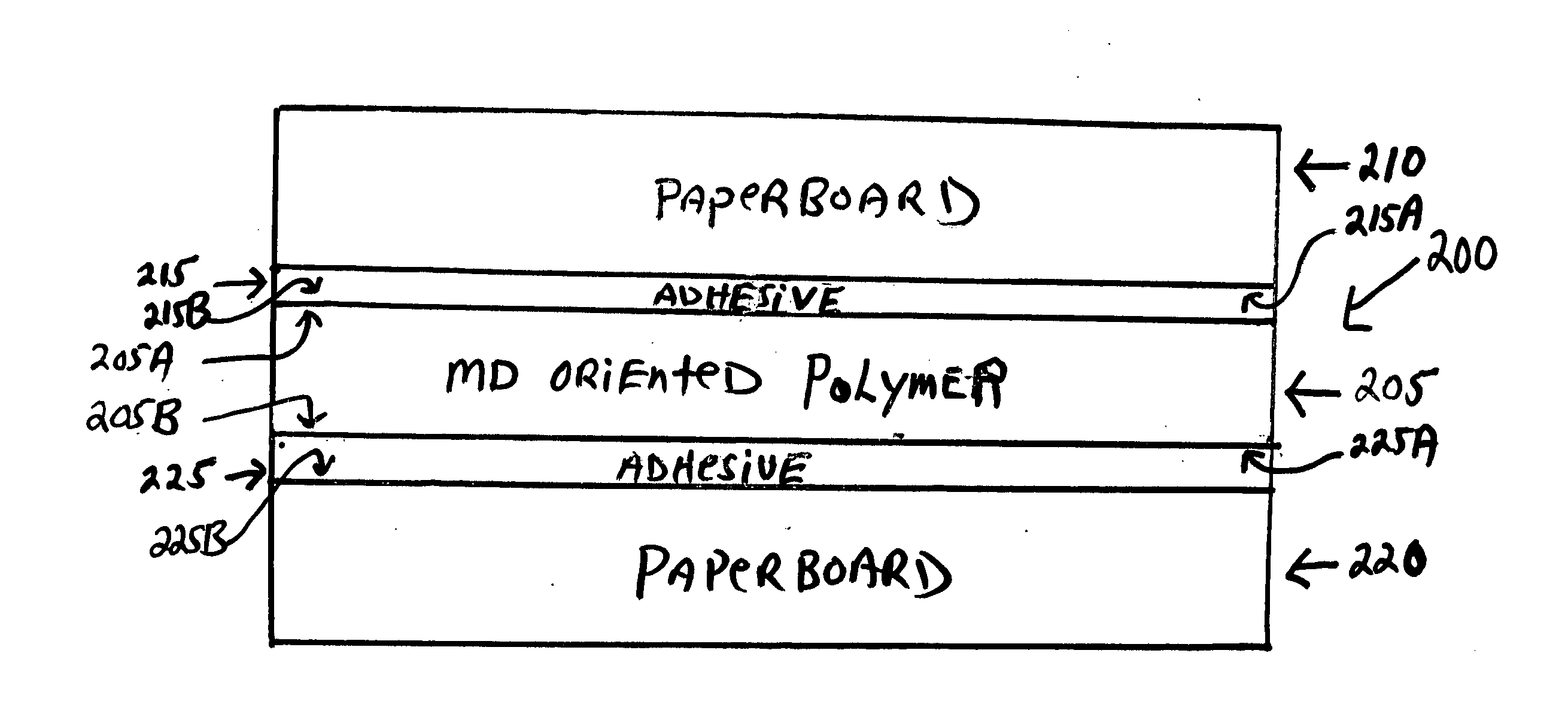
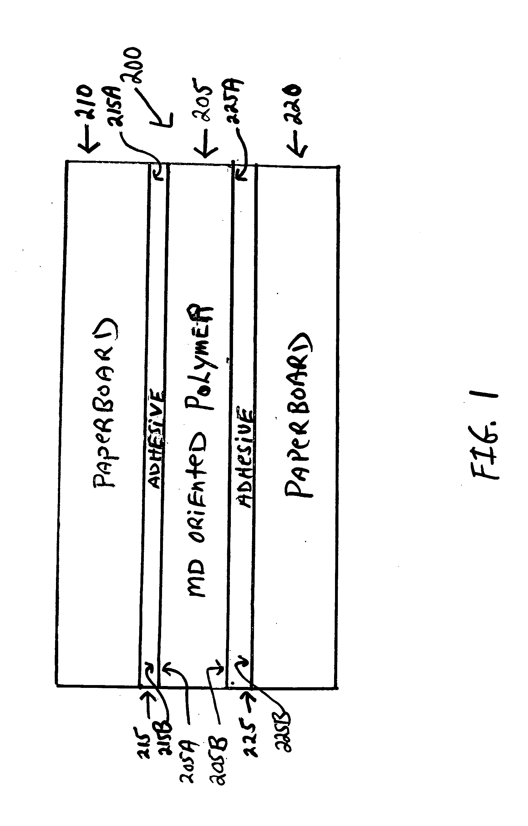
[0035]In the following description, the same numerical references refer to similar elements. The embodiments, geometrical configurations, materials mentioned and / or dimensions shown in the figures or described in the present description are preferred embodiments only, given for exemplification purposes only.

[0036]In the context of the present invention, any equivalent expression and / or compound words thereof known in the art will be used interchangeably, as apparent to a person skilled in the art. Furthermore, although the preferred embodiment of the present invention as illustrated in the accompanying drawings comprises components such as clay coatings, liquid adhesive, extrusion laminate concentrations, etc., and although the preferred embodiment of the tear-resistant paperboard laminate and corresponding parts thereof consists of certain geometrical configurations as explained and illustrated herein, not all of these components and geometries are essential to the invention, unles...


PUM

PropertyMeasurementUnit
thicknessaaaaaaaaaa
thicknessaaaaaaaaaa
tensile strengthaaaaaaaaaa

Abstract

A tear-resistant paperboard laminate includes a tear-resistant MD oriented Polyolefin core layer having first and second opposite sides. The tear-resistant paperboard laminate further includes a first paperboard layer bonded to the first side of the tear-resistant MD oriented Polyolefin core layer, with a first bonding medium. The tear-resistant paperboard laminate further includes a second paperboard layer bonded to the second side of the MD oriented Polyolefin core layer, with a second bonding medium. The first bonding medium and second bonding medium include a co-extrusion of thermoplastic material. The first bonding medium includes a first layer in contact with first paperboard layer and a second bonding medium in contact with the MD oriented Polyolefin core layer first side. A second bonding medium includes a first layer in contact with a second paperboard layer and a second layer in contact with the MD oriented Polyolefin core layer second side.

Description

CROSS-REFERENCE TO RELATED APPLICATIONS[0001]The present application is related to, claims the earliest available effective filing date(s) from (e.g., claims earliest available priority dates for other than provisional patent applications; claims benefits under 35 USC §119(e) for provisional patent applications), and incorporates by reference in its entirety all subject matter of the following listed application(s) (the “Related Applications”) to the extent such subject matter is not inconsistent herewith; the present application also claims the earliest available effective filing date(s) from, and also incorporates by reference in its entirety all subject matter of any and all parent, grandparent, great-grandparent, etc. applications of the Related Application(s) to the extent such subject matter is not inconsistent herewith:[0002]U.S. provisional patent application 61 / 963,035 entitled “Tear Resistant Paperboard Structure and Method”, naming Blair Holland as inventor, filed 21 Nov....

Claims


Application Information

Patent Timeline
Patent Type & Authority Applications(United States)
IPC IPC(8): B32B27/10B32B27/32B32B27/08
CPCB32B27/10B32B27/08B32B2250/40B32B2250/05B32B27/32B29C48/08B29C48/21B29C48/914B29C48/9155B29K2023/12B29K2311/12B32B7/12B32B2255/12B32B2255/26B32B2307/302B32B2307/54B32B2307/5825B32B2553/00Y10T428/264Y10T428/266Y10T428/31913Y10T428/31938
Inventor HOLLAND, BLAIR
Owner HOLLAND BLAIR
Why Eureka
Try Eureka