Dielectric antenna with an electromagnetic feed element and with an ellipsoidal lens made of a dielectric material

a dielectric material and dielectric antenna technology, applied in the direction of antennas, basic electric elements, electric apparatus, etc., can solve the problems of dielectric antennas, high requirements for attainable hygiene, and contradictory requirements with respect, so as to minimize the number of intermediate spaces and transition sites between the lens and the electromagnetic feed element. , the effect of good encapsulation of the antenna

Active Publication Date: 2014-12-23
KROHNE MESSTECHNICK GMBH & CO KG
View PDF8 Cites 239 Cited by
  • Summary
  • Abstract
  • Description
  • Claims
  • Application Information

AI Technical Summary

Benefits of technology

[0009]Therefore, the object of this invention is to at least partially avoid the above indicated disadvantages of the known dielectric antennas.
[0010]This object is achieved in accordance with the invention, first of all, essentially in the dielectric antenna under consideration, in that the lens is shaped ellipsoidally at least in the transmission region and the lens is arranged relative to the feed element such that the electromagnetic radiation emitted by the lens in the direction of maximum radiation of the antenna has an essentially planar phase front. It has been ascertained that ellipsoidally shaped dielectric lenses enable a very short type of construction with simultaneous generation of emitted electromagnetic radiation which has essentially a planar phase front in the direction of maximum radiation.
[0011]In one preferred configuration of the invention, the dielectric lens is axisymmetrical to the major axis of the ellipsoid defined by the at least ellipsoidally shaped transmission region of the lens, the major axis of the ellipsoid then pointing essentially in the direction of maximum radiation of the antenna. Here, as is conventional in geometry, the major axis of an ellipsoid or the major axis of an ellipse is defined as the longitudinal axis of the ellipsoid or the ellipse, therefore that axis on which the focal points of the ellipsoid or the ellipse lie. These asymmetrical lenses are even rotationally symmetrical and therefore can be produced and installed especially easily.
[0018]On the one hand, in this way, very good encapsulation of the antenna is implemented altogether so that the dielectric antenna is also suitable for applications which have especially high demands with respect to attainable hygiene, such as, for example, applications in the food industry. Because the lens surrounds the electromagnetic feed element and the hollow conductor, the number of intermediate spaces and transition sites between the lens and electromagnetic feed element is minimized.
[0019]On the other hand, due to the shape of the dielectric lens and as a result of the lack of metallic jacketing of the lens altogether, an effective aperture is achieved which is larger than the antenna aperture perceived only by projection of the transmission region of the lens in the direction of maximum radiation, so that the dielectric antenna in accordance with the invention achieves greater gain than, for example, a horn radiator of the same size. In addition, the open structure which, different from a rod radiator, does not form a waveguide, provides for repeated reflections of the impulse response decaying rapidly.

Problems solved by technology

However, these requirements are contradictory with respect to the mechanical measures which must be conventionally taken for their technical implementation.
So that the aperture is also used for purposes of a narrow direction of maximum radiation, the electromagnetic radiation emitted from the transmission region of the lens must have a phase front as planar as possible, and this planar phase front can be implemented more easily with increasing length of the antenna; likewise, this opposes the desired compact type of construction.
Known dielectric antennas, in addition to difficult simultaneous implementation of a narrow direction of maximum radiation with a simultaneously compact type of construction, have a further disadvantage which is related to the mutual arrangement of the electromagnetic feed element and the lens made of dielectric material.
The two aforementioned versions have the disadvantage that a type of construction which is also suitable, for example, for hygiene applications can only be poorly implemented.
Aside from the implementation of an antenna with a lens which is at least partially encompassed by the feed element, which implementation is mechanically very demanding anyway, this type of construction also has the disadvantage that the transition from the feed element to the lens is in a region of the antenna that is shifted far forward and is comparatively exposed, and therefore, susceptible to dirt.
In an antenna construction with intermediate spaces between the electromagnetic feed element and the lens, there is always the danger of fouling of those antenna surfaces which face the intermediate space; furthermore, overpressure and underpressure applications can be a problem as a result of the existing intermediate space.

Method used


Image

  • Dielectric antenna with an electromagnetic feed element and with an ellipsoidal lens made of a dielectric material
  • Dielectric antenna with an electromagnetic feed element and with an ellipsoidal lens made of a dielectric material
  • Dielectric antenna with an electromagnetic feed element and with an ellipsoidal lens made of a dielectric material

Examples


Embodiment Construction

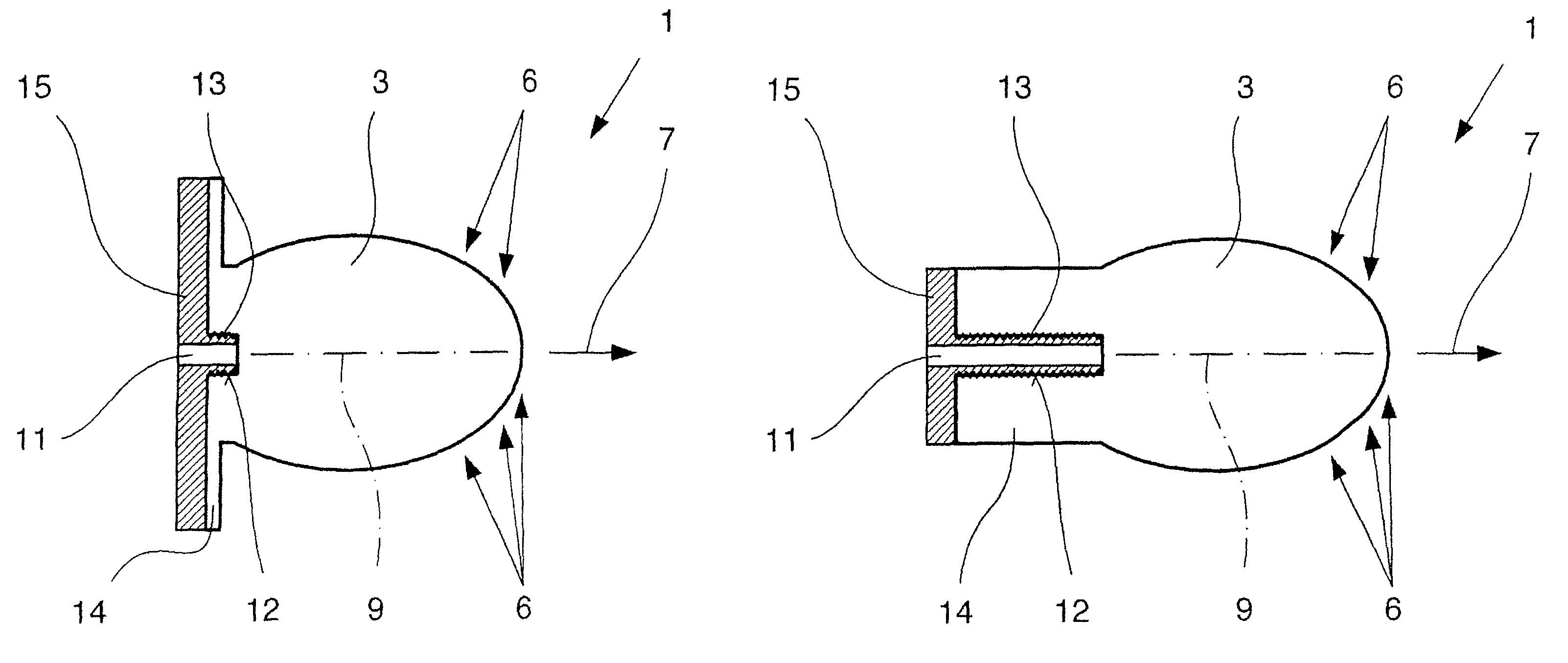
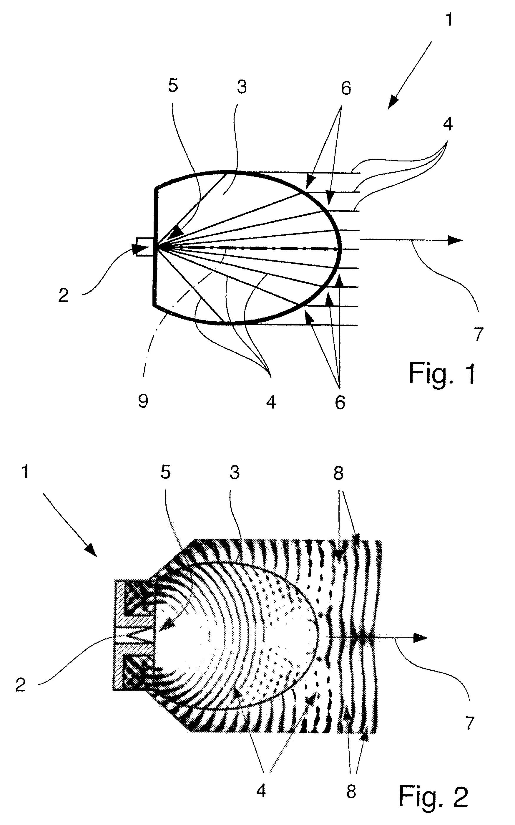
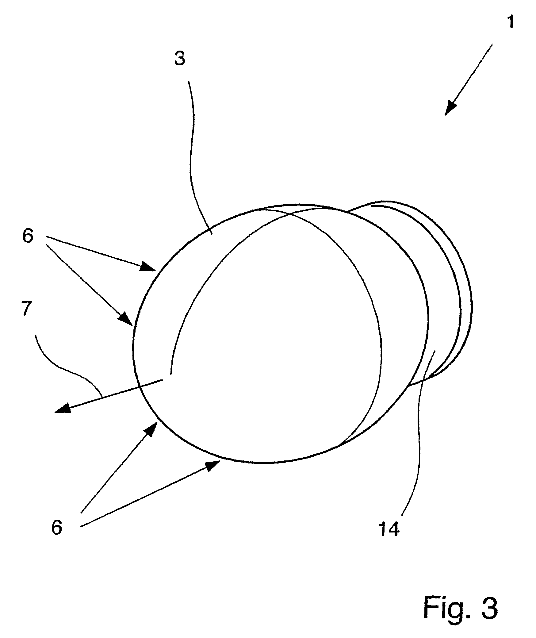
[0032]FIGS. 1 to 7 show a dielectric antenna 1 with an electromagnetic feed element 2 and with a lens 3 made of a dielectric material. The manner of operation of the antenna 1 is always based on the feed element 2 emitting electromagnetic radiation 4 and the lens 3 being supplied with electromagnetic radiation 4 in the feed region 5, the lens 3 relaying the electromagnetic radiation 4 and emitting it with the transmission region 6 of the lens.

[0033]In all figures it is shown that the lens 3 is shaped ellipsoidally at least in the transmission region 6 and the lens 3 is arranged relative to the feed element 2 such that the electromagnetic radiation 4 emitted from the lens 3 in the direction of maximum radiation 7 of the antenna 1 has an essentially planar phase front 8, the phase front 8 being explicitly recognizable only in FIG. 2.

[0034]FIG. 1 clearly shows how the electromagnetic radiation 4 which has been emitted from the schematically shown feed element 2 propagates within the le...


PUM


Abstract

A dielectric antenna with an electromagnetic feed element (2) and with a lens (3) made of a dielectric material, the feed element (2) emitting electromagnetic radiation (4) and the lens (3) being supplied with electromagnetic radiation (4) in the feed region (5), the lens (3) relaying the electromagnetic radiation (4) and radiating it with the transmission region (6). To configure these dielectric antennas such that the disadvantages of the dielectric antennas known from the prior art are at least partially avoided, first of all, the lens (3) is shaped essentially ellipsoidally at least in the transmission region (6) and the lens (3) is arranged relative to the feed element (2) such that the electromagnetic radiation (4) emitted by the lens (3) in the direction of maximum radiation (7) of the antenna has an essentially planar phase front.

Description

BACKGROUND OF THE INVENTION[0001]1. Field of the Invention[0002]The invention relates to a dielectric antenna with an electromagnetic feed element and with a lens made of a dielectric material, the feed element emitting electromagnetic radiation and the lens in the feed region being supplied with electromagnetic radiation, the lens relaying the electromagnetic radiation and emitting it with the transmission region.[0003]2. Description of Related Art[0004]Dielectric antennas are known from various fields of engineering in quite varied types of construction. However, it is common to dielectric antennas that dielectric materials, especially those dielectric materials which have especially low losses, are used to guide and radiate electromagnetic waves. For example, using polytetraflouroethylene or polypropylene as the dielectric material or other dielectrics with low permittivity for the lens is known.[0005]In industrial process engineering, dielectric antennas are often used, for exam...

Claims


Application Information

Patent Timeline
Patent Type & Authority Patents(United States)
IPC IPC(8): H01Q19/08H01Q15/08H01Q19/09H01Q13/06
CPCH01Q19/09H01Q13/06H01Q15/08
Inventor POHL, NILS
Owner KROHNE MESSTECHNICK GMBH & CO KG
Why Eureka
Try Eureka