Optical device

a technology of optical devices and optical components, applied in the direction of optical elements, electromagnetic radiation sensing, instruments, etc., can solve the problems of lack of adequate control over the brightness of the aim point, difficulty in properly aiming relative to the target area, and difficult to view the point, so as to reduce the cost of production, simplify the design and components of the control system, and achieve the effect of reducing the cost of production

Inactive Publication Date: 2014-12-30
BROWE
View PDF46 Cites 12 Cited by
  • Summary
  • Abstract
  • Description
  • Claims
  • Application Information

AI Technical Summary

Benefits of technology

[0009]Since the light sensor is mounted to the circuit board and extends from the circuit board through the tube wall into the viewing bore, the design and components of the control system are advantageously simplified. The simplified design and components advantageously reduce the cost to produce the optical device. Further, the compact design advantageously minimizes the overall size and weight of the control system. In addition, since the overall size and weight of the control system is minimized, the compact size and weight of the control system is easily balanced so that the optical device has a balanced weight distribution.

Problems solved by technology

Depending upon light conditions, the aim point can be difficult to view and can be difficult to properly aim relative to the target area.
However, a major disadvantage to an illuminated aim point is the lack of adequate control over the brightness of the aim point.
If the illuminated aim point is too dim compared to the target area, then the illuminated aim point is difficult to view.
On the other hand, if the illuminated aim point is too bright then the illuminated aim point interferes with the view of the target area.
In addition, systems that illuminate the aim point are also expensive and disadvantageously add size and weight to the optical device while disadvantageously causing an imbalance in the weight distribution of the optical device.

Method used


Image

  • Optical device
  • Optical device
  • Optical device

Examples


Embodiment Construction

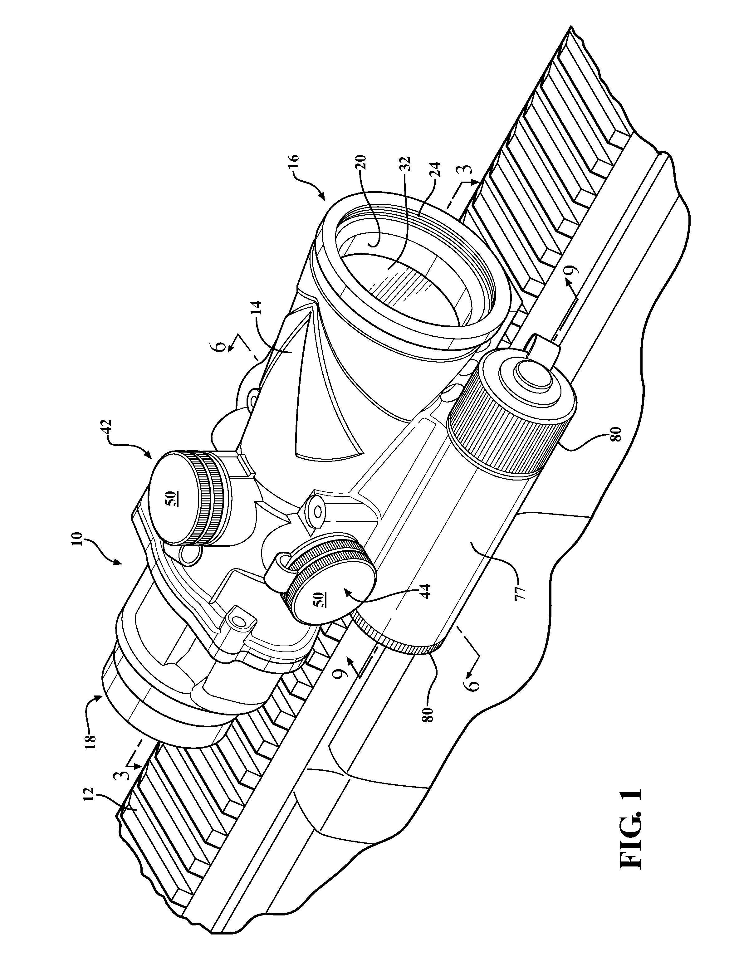
[0023]Referring to the Figures, wherein like numerals indicate like parts throughout the several views, an optical device 10 is generally shown for magnifying a distant target area (not shown). With reference to FIG. 1, the optical device 10 can be mounted on a firearm 12 such as, for example, a military or police assault rifle such as an M4 or M16 / AR15. However, the optical device 10 can be mounted on any type of firearm including military, police, or civilian, without departing from the nature of the present invention. Alternatively, the optical device 10 can be used independently from a firearm and can be, for example, binoculars, a spotting scope, etc. The optical device 10, for example, is a 4×32 magnified optic. In any event, the optical device 10 is typically waterproof, for example, up to 100 ft.

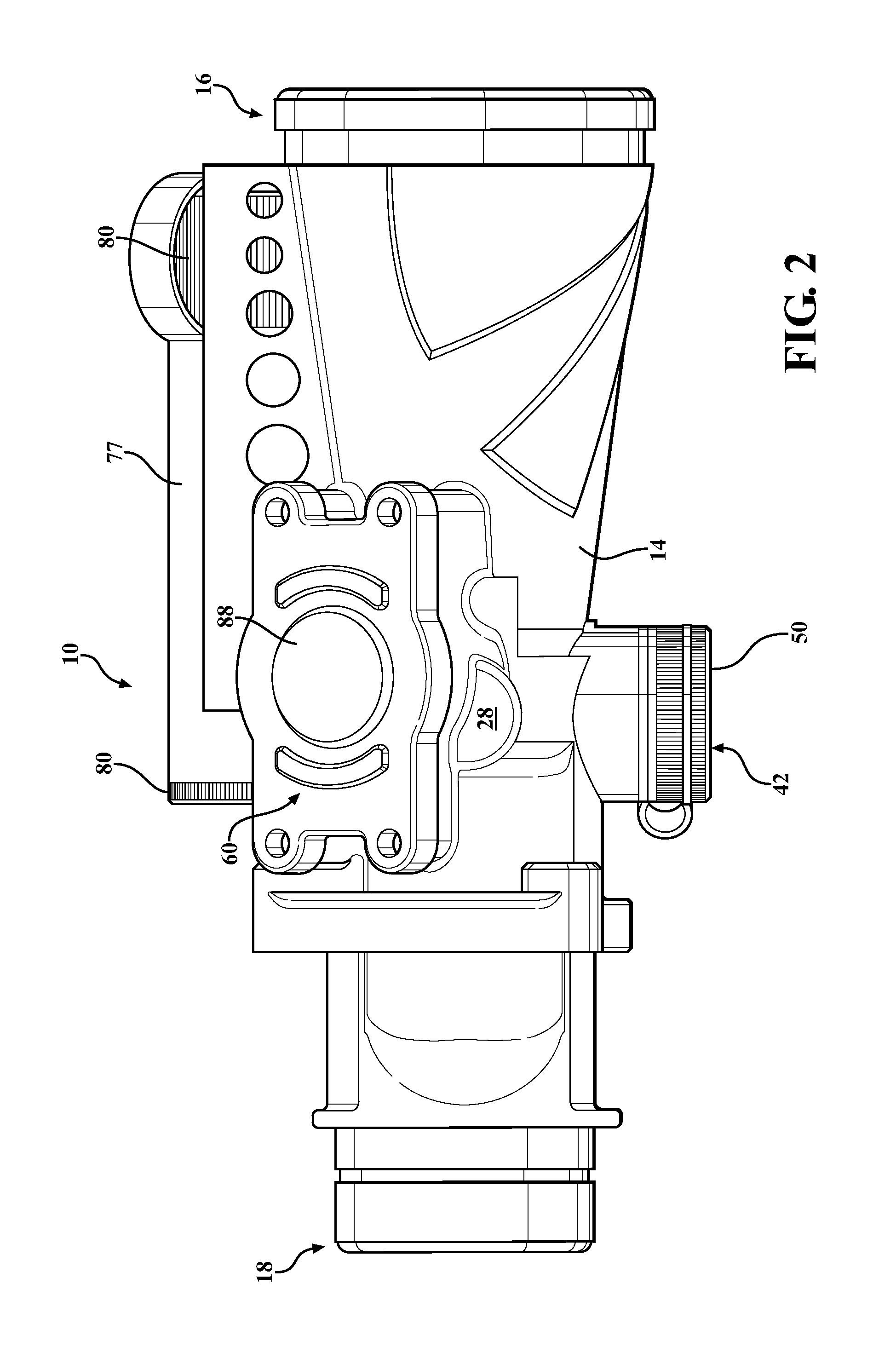
[0024]With reference to FIGS. 1-3, the optical device 10 includes a tube 14 extending between an objective end 16 and an ocular end 18 and defining a viewing bore 20 extending from t...


PUM


Abstract

An optical device has a tube including a tube wall defining a viewing bore. A light source is in communication with the viewing bore for illuminating an aim point visible in the viewing bore. A control system includes a circuit board supported by the tube exterior of the viewing bore. The control system is in communication with the light source for controlling brightness of the illuminated aim point. The control system includes a light sensor mounted to the circuit board and extending from the circuit board through the tube wall into the viewing bore for sensing light in the viewing bore.

Description

CROSS-REFERENCE TO RELATED APPLICATIONS[0001]The subject patent application claims priority to and all the benefits of U.S. Provisional Patent Application No. 61 / 343,970, which was filed on May 6, 2010, the entire specification of which is expressly incorporated herein by reference.BACKGROUND OF THE INVENTION[0002]1. Field of the Invention[0003]The present invention relates to an optical device and, more specifically, an optical device that includes an illuminated aim point.[0004]2. Description of the Related Art[0005]Optical devices are used for magnifying a distant target area and can be mounted on a firearm. The optical device includes a tube having an objective end, an ocular end, and a viewing bore extending from the objective end to the ocular end. Typically, an objective lens is mounted in the bore at the objective end, an ocular lens is mounted in the bore at the ocular end, and an optic is mounted in the viewing bore between the objective lens and the ocular lens.[0006]An a...

Claims


Application Information

Patent Timeline
Patent Type & Authority Patents(United States)
IPC IPC(8): F41G1/34G02B27/34H05B37/02G02B23/10
CPCG02B27/34G02B23/105F41G1/345
Inventor BROWE, BRIAN K.SCHAUPETER, BRIAN S.GRABAN, JON
Owner BROWE
Why Eureka
Try Eureka