
Root canal length measuring apparatus and root canal therapy apparatus

a technology of root canal and measuring apparatus, which is applied in the field of root canal length measuring apparatus and root canal treatment apparatus, can solve the problems of adding the impedance value of the root canal to the difference in the impedance of the root canal, and achieve the effect of high reproducibility

Active Publication Date: 2014-12-30
MORITA MFG CO LTD
View PDF45 Cites 3 Cited by
  • Summary
  • Abstract
  • Description
  • Claims
  • Application Information

AI Technical Summary

Benefits of technology

[0020]It is an object of the present invention to provide a root canal length measuring apparatus and a root canal treatment apparatus which can acquire a position of a measurement electrode with high reproducibility in the same root canal.
[0024]The root canal length measuring apparatus of the present invention has the memory means which stores display data and the operating means which instructs the memory means to store the display data. For this reason, a positional relationship between the position of the measurement electrode in the same root canal and the stored position data stored can be acquired with high reproducibility.
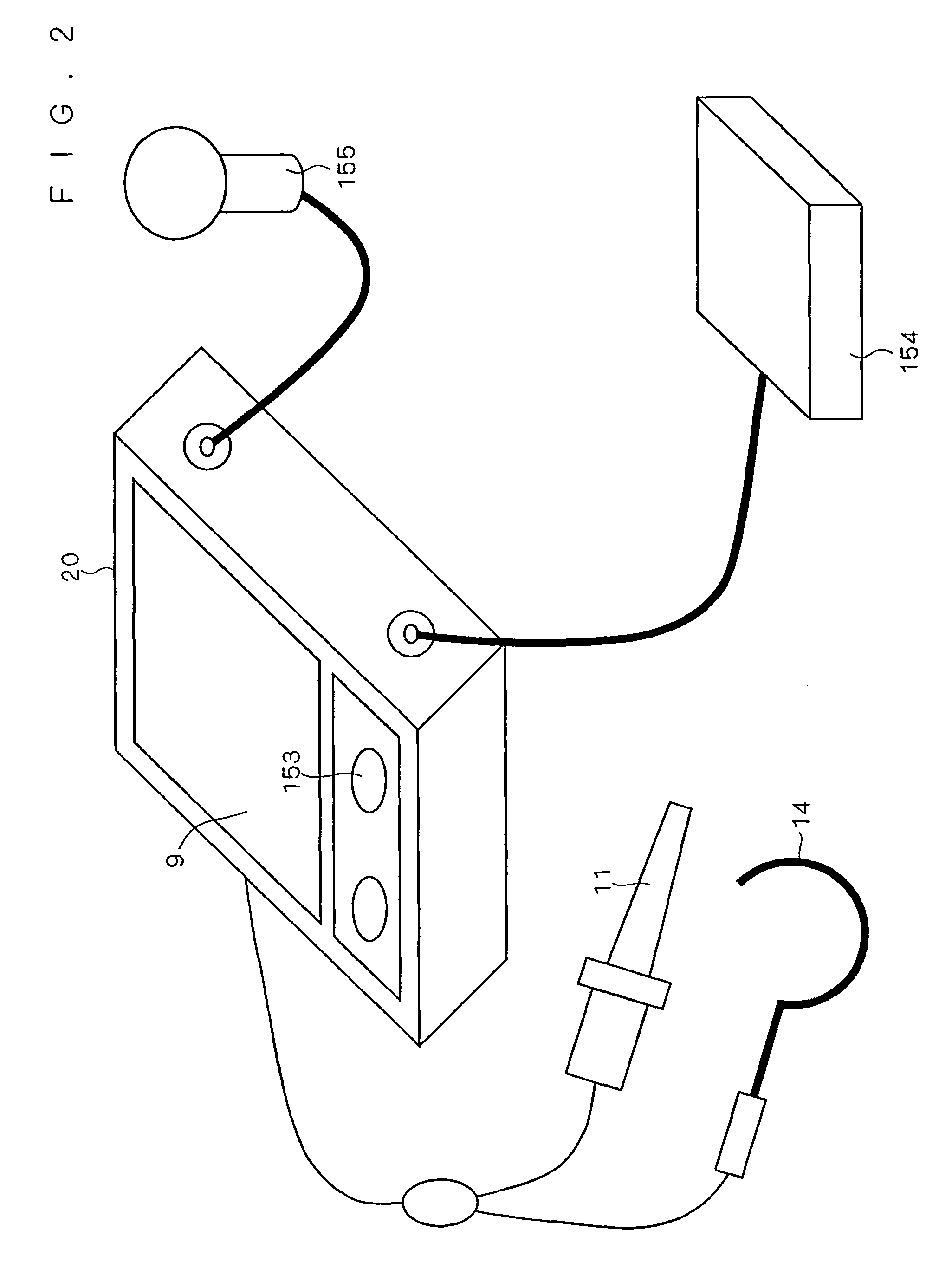
[0026]The root canal treatment apparatus of the present invention can control the driving section on a desired position of the measurement electrode with high reproducibility in the same root canal, and can do the root canal treatment easily and accurately. In the root canal treatment apparatus, the root canal treatment tool for the root canal treatment can serve also as the measurement electrode for the root canal length measurement. For this reason, a complicated operation for replacing the electrode and tool is not required, and the measurement of the root canal length and the root canal treatment can be made simultaneously, namely, this apparatus is convenient.

Problems solved by technology

This method, however, occasionally requires such adjustment that the impedance value in the root canal is added to a difference in the impedance in the root canal.

Method used


Image

  • Root canal length measuring apparatus and root canal therapy apparatus
  • Root canal length measuring apparatus and root canal therapy apparatus
  • Root canal length measuring apparatus and root canal therapy apparatus

Examples


first embodiment

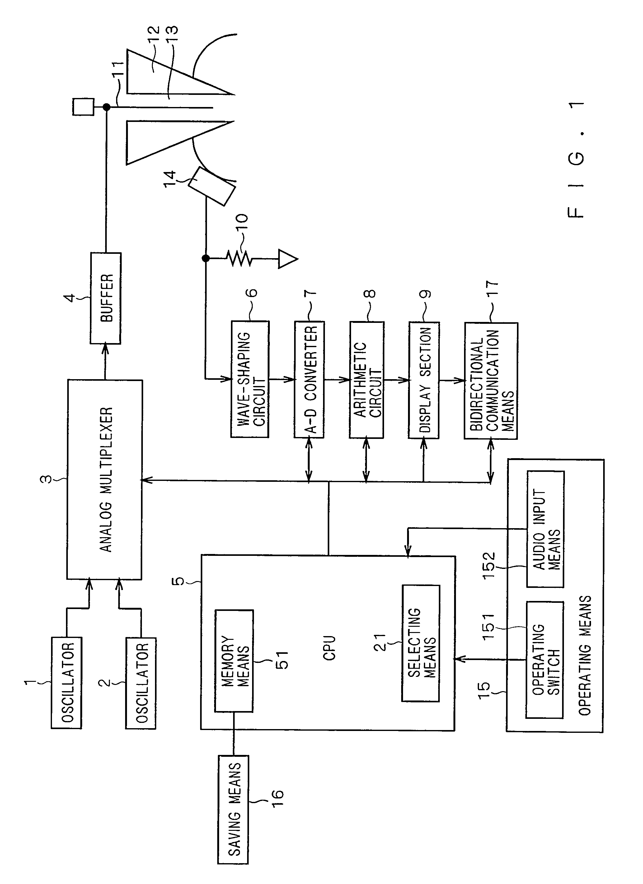
[0053]FIG. 1 is a block diagram illustrating the root canal length measuring apparatus according to the first embodiment. The root canal length measuring apparatus shown in FIG. 1 has an oscillator 1 which outputs a measuring signal having a predetermined frequency, and an oscillator 2 which outputs a measuring signal having a frequency different from the oscillator 1. Further, the root canal length measuring apparatus shown in FIG. 1 has an analog multiplexer 3, a buffer 4 and a CPU 5. The root canal length measuring apparatus shown in FIG. 1 further has a wave-shaping circuit 6, an A-D converter 7, an arithmetic circuit 8, a display section 9 and a detecting resistor 10.

[0054]In the root canal length measuring apparatus shown in FIG. 1, a measurement electrode 11 connected to the buffer 4 is inserted into a root canal 13 of a tooth 12, and a change in impedance in the root canal between an oral electrode 14 connected to the detecting resistor 10 and the measurement electrode 11 is...

second embodiment

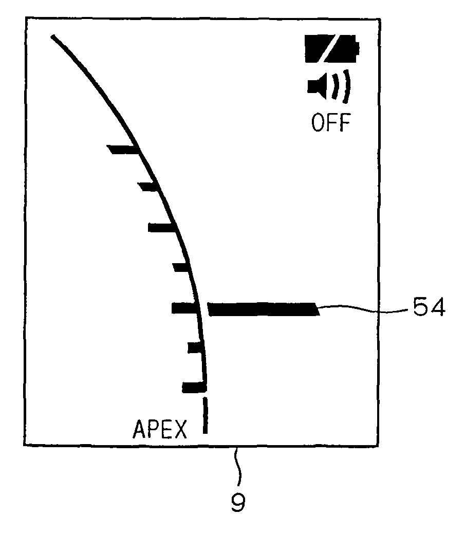
[0074]A method for measuring an accurate position from an apex with high reproducibility in the root canal length measuring apparatus according to the second embodiment is described below. In the conventional root canal length measuring apparatus, scale marks 1, 2 and 3 are given to the indicator of the display section. A value indicated by the scale marks is a distance from an apex obtained by an average value of results of measuring the distances from a lot of root canals, and thus these scale marks are given as only guides. For example, even if the display section indicates the scale mark 1, it is not ensured that the measurement electrode is present on a position −1.0 mm away from the apex. As the measurement electrode is moved away from the apex by −2.0 mm and −3.0 mm, its error becomes larger, and thus these scale marks cannot be practically used.

[0075]The conventional root canal length measuring apparatus can approximately accurately detect the apex position although the meas...

third embodiment

[0086]In even some conventional root canal length measuring apparatuses, scale marks are provided to the indicator. These marks show only average values of corresponding root canal positions obtained by detecting impedance values in a lot of root canals, a ratio of the impedance values and a difference in the impedances. Specifically, an example of the conventional root canal length measuring apparatus for detecting the ratio of the impedance in a root canal is described. In the conventional root canal length measuring apparatus, when the measurement electrode 11 arrives at an apex, the ratios of the impedances in the root canal measured at a plurality of frequencies obtains approximately predetermined constant values, and indicates APEX.

[0087]In the conventional root canal length measuring apparatus, scale marks 1, 2 and 3 are given to the indicator correspondingly to the positions −1 mm, −2 mm and −3 mm as average values obtained by measuring a lot of root canals. That is to say, ...


PUM


Abstract

The present invention provides a root canal length measuring apparatus and a root canal treatment apparatus which can acquire a position of a measurement electrode with high reproducibility in the same root canal. The root canal length measuring apparatus includes a measurement electrode which is inserted into a root canal, an oral electrode which is held in an oral cavity, a measuring section which applies an electric measuring signal between the measurement electrode and the oral electrode and specifies an apex position so as to measure a root canal length, a memory means which stores position data corresponding to a position of the measurement electrode in a root canal acquired by the measuring section, and an operating means which instructs the memory means to store the position data.

Description

BACKGROUND OF THE INVENTION[0001]1. Field of the Invention[0002]The present invention relates to a root canal length measuring apparatus and a root canal treatment apparatus which are used for dental treatment and diagnosis.[0003]2. Description of the Background Art[0004]As shown in FIG. 16, a human tooth is composed of an enamel 101, a dentin 102 and a cementum 103. The tooth is supported by an alveolar bone 104 and a gum 105. A dental pulp 106 is present inside the tooth, and blood vessels and nerves pass from the dental pulp 106 through a root canal 107 so as to be connected to blood vessels below the alveolar bone 104. Ends of the root canal 107 on side of the alveolar bones 104 are called as an apex 108.[0005]A root membrane 109 is present on a boundary between a tooth root of the cementum 103 including the apex 108 and the alveolar bone 104. The root membrane 109 is a membrane which covers the entire tooth root of the tooth 101 as shown in FIG. 17. As shown in FIG. 17, the roo...

Claims


Application Information

Patent Timeline
Patent Type & Authority Patents(United States)
IPC IPC(8): A61C19/04A61C1/00
CPCA61C19/042A61C19/041
Inventor YAMASHITA, SEIICHIROKUSAKABE, HIROAKIMATOBA, KAZUNARIITO, TETSUZO
Owner MORITA MFG CO LTD
Learn More