Gravity cup for a paint sprayer

a sprayer and gravity cup technology, applied in the direction of caps, closures using caps, closure stoppers, etc., can solve the problems of leakage of tanks known from the state of the art, and achieve the effect of improving tightness

Active Publication Date: 2015-01-06
SATA GMBH & CO KG
View PDF472 Cites 41 Cited by
  • Summary
  • Abstract
  • Description
  • Claims
  • Application Information

AI Technical Summary

Benefits of technology

[0005]The goal of the invention is to further develop the gravity cups of the types mentioned in the preamble, so that they have an improved tightness between the tank and the cover set on it.
[0007]With the gravity cup in accordance with the invention, which comprises a cup-shaped tank and a cover which can be placed on the tank, a multiplex quick-connect thread with at least two external thread turns and internal thread turns, acting together with the external thread turns, is provided for the connection of the tank and the cover, wherein each external thread turn is formed by a plurality of thread segments located along the slope line of the individual external thread turn. A gap is formed between adjacent thread segments. In this way, wall thickness aggregations that appear in the area of the external thread turns during the injection molding, are largely avoided and the upper rim of the tank has a constant rigidity over the external circumference, which leads to an improved tightness when the cover is screwed on the tank via the quick-connect thread.
[0008]The external thread turns are preferably shaped on the upper external circumference of the tank, and the internal thread turns are located on the cover. However, it is also possible to place the external thread turns on the cover and the internal thread turns on the external circumference of the tank. Furthermore, at least one ramp is preferably provided on each external thread turn, which makes possible an improved and especially, a smooth screwing behavior when the cover is screwed on the tank. The guide ramp(s) are appropriately placed on the upper side of each external thread turn, in particular, on the upper side of two adjacent thread segments. In a preferred embodiment, the guide ramps are located between two adjacent thread segments—that is, above the gap—and bridging the two adjacent thread segments.
[0009]In a preferred embodiment example, the internal thread turns are located on the inside of a flange on the cover and on the internal circumference of the flange, in the direction of closing of the quick-connect thread, tapering in an axial direction. Upon placing the cover on the tank rim, the guide ramps located on the upper side of each external thread turn act as guide aids and upon screwing the quick-connect thread, the guide ramps mesh into the internal thread turns on the cover and are wedged there as a result of the tapering of the internal thread turn in the closing direction of the quick-connect thread. In this way, a firm seat of the screwed quick-connect thread is guaranteed, which cannot become loosened by itself—for example, because of vibrations during the injection process.

Problems solved by technology

over the circumference, the tanks known from the state of the art tend to have leaks, especially with a local deformation if the tank is compressed when it is being manually handled in the upper rim area.

Method used


Image

  • Gravity cup for a paint sprayer
  • Gravity cup for a paint sprayer
  • Gravity cup for a paint sprayer

Examples


Embodiment Construction

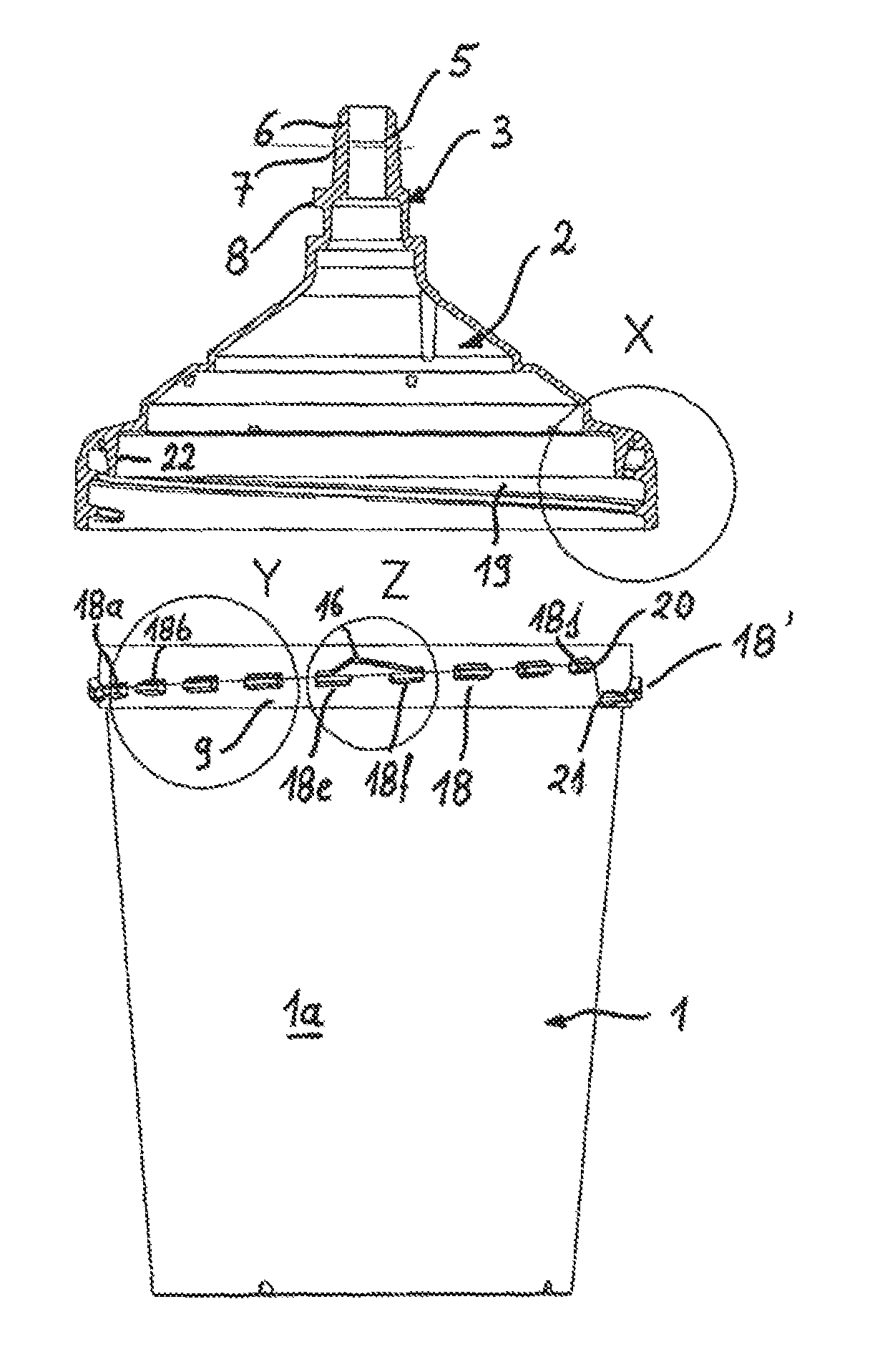
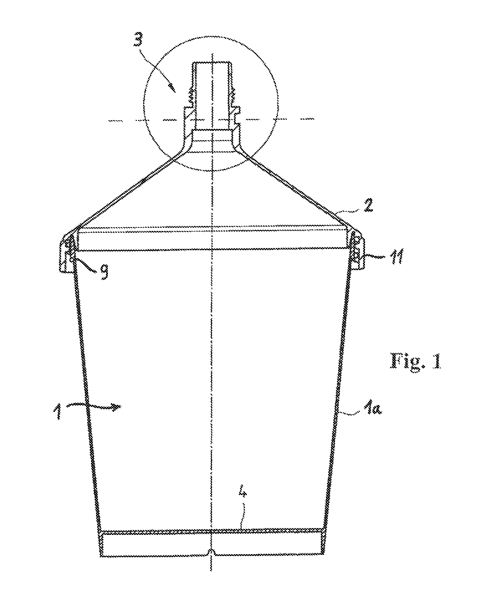
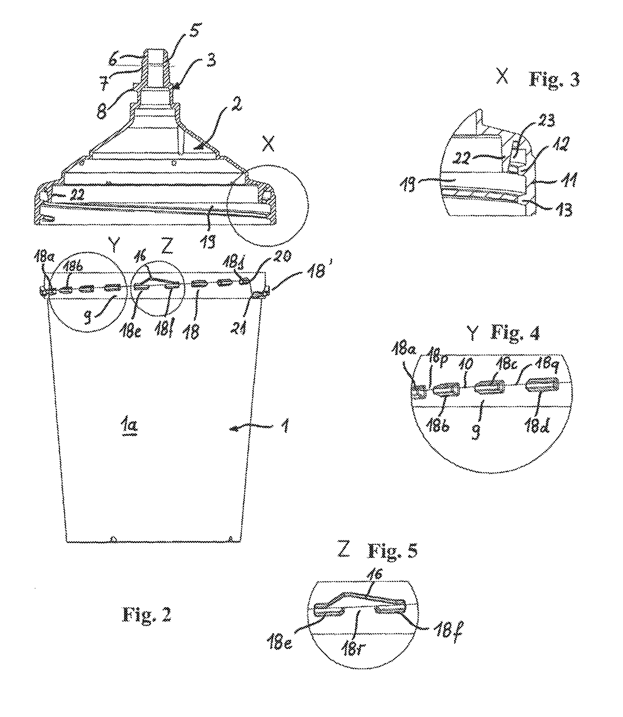
[0018]The gravity cup for a paint sprayer, shown in sectional view in FIG. 1, comprises a cup-shaped tank 1 and a cover 2, placed on it, on which a connecting part 3 is shaped, for the detachable affixing of the gravity cup on a paint sprayer. Both the tank 1 and the cover 2 with the shaped connecting part 3 are appropriately produced as injection moldings made of plastic. FIG. 2 shows the gravity cup with the cover 2 removed from the tank 1, in a side view. In the position shown in FIG. 2, with the removed cover 2, the cup-shaped tank 1 is filled with a liquid, in particular, a paint, to be sprayed by means of a paint sprayer. Subsequently, the cover 2 is placed on the upper rim of the tank and screwed with the tank via a quick-connect thread. Then, the gravity cup can be inserted, with the connecting part 3 shaped on the cover 2, into the connecting opening of a paint sprayer placed on its head. For the spraying, the paint sprayer can then be turned around, so that the gravity cup...


PUM


Abstract

The invention relates to a gravity cup for a paint sprayer, having a cup-shaped tank (1) and a cover (2) that can be placed on the tank (1), a multiplex quick-connect thread having at least two external thread turns (18) and internal thread turns (19) engaging with the external thread turns (18) for connecting the tank (1) and the cover (2), characterized in that each external thread turn (18) is formed of a plurality of thread segments (18a, 18b, 18j) disposed along the pitch line of each external thread turn, wherein a gap (18p, 18q . . . 18w) is formed between adjacent thread segments.

Description

FIELD OF THE INVENTION[0001]The invention concerns a gravity cup for a paint sprayer according to the preamble of claim 1.BACKGROUND OF THE INVENTION[0002]Traditional gravity cups for paint sprayers usually have a cup-shaped tank, on whose lower side, an opening with a connecting part for the detachable affixing of the tank on the upper side of the paint sprayer is provided. The connecting part usually consists of a connecting piece inserted into the tank bottom, which has an external thread for screwing into a corresponding thread opening on the upper side of the paint sprayer. As a rule, the cup-shaped tank is closed on its upper side by a suitable cover, which is meant to prevent an undesired discharge of the paint.[0003]Gravity cups, which comprise a cup-shaped tank and a cover with a hollow-cylindrical connecting part that can be placed on it, are already known from WO 01 / 12337 A1, WO2004 / 037433 A1, EP 1 366 823 A1, and EP 1902786 A1. The connecting part there comprises a conne...

Claims


Application Information

Patent Timeline
Patent Type & Authority Patents(United States)
IPC IPC(8): B05B7/24B05B9/01B05B9/03B65D41/04B65D39/08
CPCB05B7/2408B05B7/2478
Inventor DETTLAFF, PETERLEIPOLD, KLAUS
Owner SATA GMBH & CO KG
Why Eureka
Try Eureka