
Fluid dynamic bearing device

a technology of dynamic bearings and bearing devices, which is applied in the direction of sliding contact bearings, instruments, and record information storage, etc., can solve the problems of high production cost, increased cost of forming dynamic pressure generating grooves, and high manufacturing cost of fluid dynamic bearing devices, so as to achieve low cost, less time and effort, and high bearing rigidity

Inactive Publication Date: 2015-01-06
NTN CORP
View PDF43 Cites 4 Cited by
  • Summary
  • Abstract
  • Description
  • Claims
  • Application Information

AI Technical Summary

Benefits of technology

This patent describes a new design for a fluid dynamic bearing device that is cheaper and more rigid than previous versions. The design also allows for easier and more accurate formation of recessed portions for generating fluid dynamic pressure in the radial bearing gaps, which reduces the cost of the device while still providing good performance. Additionally, the design allows for easy manufacture of a flanged shaft member that is accurate and strong, providing excellent rotational accuracy in the thrust directions at a low cost.

Problems solved by technology

As a result, the core rod and the dies are liable to be subjected to abrasion and the like, and hence the dies need to be frequently replaced, which causes an increase in cost of forming the dynamic pressure generating grooves, by extension, manufacturing cost of the fluid dynamic bearing device.
However, in addition to requirement of dedicated processing equipment, material loss is significant, and hence markedly high production cost is required.

Method used


Image

  • Fluid dynamic bearing device
  • Fluid dynamic bearing device
  • Fluid dynamic bearing device

Examples


first embodiment

[0136]FIG. 6 illustrates the fluid dynamic bearing device 101 according to this invention. The fluid dynamic bearing device 101 comprises, as components, the bearing member 109 opened at both axial end portions, the shaft member 102 inserted along an inner periphery of the bearing member 109, and a lid member 110 for closing an opening of one of the end portions of the bearing member 109. A lubricating oil as a lubricating fluid (indicated by densely dotted hatching) is filled in an internal space. In this embodiment, the bearing member 109 comprises a bearing sleeve 108 having an inner periphery along which the shaft member 102 is inserted, and a housing 107 having an inner periphery on which the bearing sleeve 108 is held (fixed). Note that, for the sake of convenience in description, a side on which the lid member 110 is hereinafter provided is referred to as a lower side, and an opposite side thereto in the axial direction is hereinafter referred to as an upper side.

[0137]The be...

second embodiment

[0170]FIG. 11 is an axial sectional view of a fluid dynamic bearing device 101 according to this invention. The fluid dynamic bearing device 101 illustrated in FIG. 11 is different from that illustrated in FIG. 6 mainly in that the housing 107 integrally comprises a disk-like bottom portion 107c for closing the lower end of the cylindrical main body portion 107a and that the sealing space S is formed with a ring-like sealing member 112 fixed to an inner periphery of the upper end of the main body portion 107a. In other words, the second thrust bearing gap of the second thrust bearing portion T2 is formed between the lower end surface 122b of the flange portion 122 and an upper end surface 107c1 of the housing bottom portion 107c. Further, the sealing space S is formed between an inner peripheral surface 112a of the sealing member 112 and the outer peripheral surface 121a of the shaft portion 121. Note that, a step portion 107d is provided at a boundary portion between the main body ...

third embodiment

[0171]FIG. 12 is an axial sectional view of a fluid dynamic bearing device 101 according to this invention. The fluid dynamic bearing device 101 illustrated in FIG. 12 is different from that illustrated in FIG. 6 mainly in the following points. The disk hub 103 integrally comprises an annular portion 103a and a cylindrical portion 103b extending in the axial direction from a radially outer end of the annular portion 103a, and is provided at an upper end portion of the shaft member 102 (shaft portion 121). The second thrust bearing gap of the second thrust bearing portion T2 is provided between a lower end surface 103a1 of the annular portion 103a of the disk hub 103 and an opposing upper end surface 107a4 of the housing 107 (main body portion 107a). The sealing space S is provided between an upper outer peripheral surface 107a5 of the housing 107 and an inner peripheral surface 103b1 of the cylindrical portion 103b of the disk hub 103. Further, in this embodiment, the shaft portion ...


PUM

PropertyMeasurementUnit
densityaaaaaaaaaa
densityaaaaaaaaaa
surface porositiesaaaaaaaaaa

Abstract

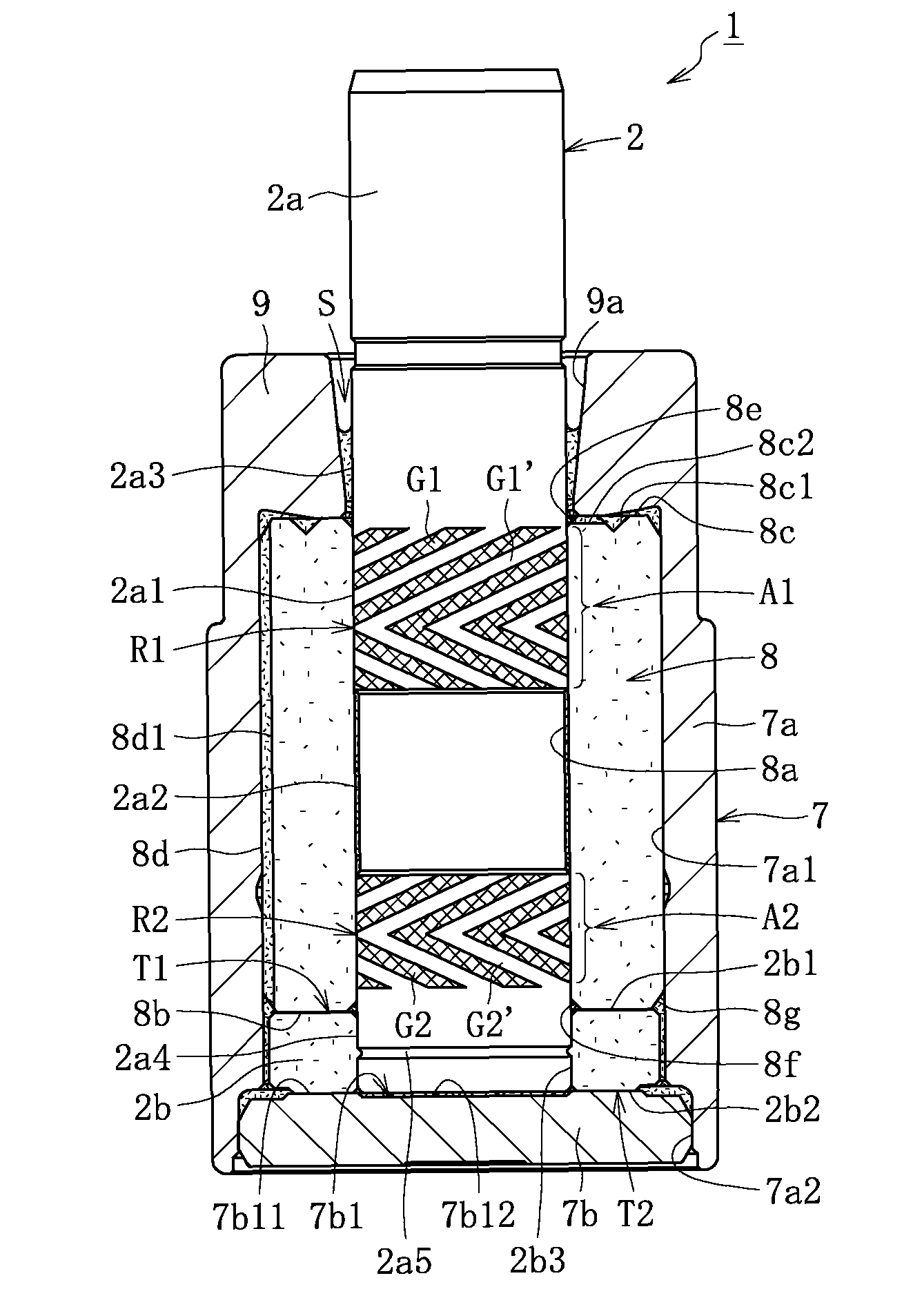
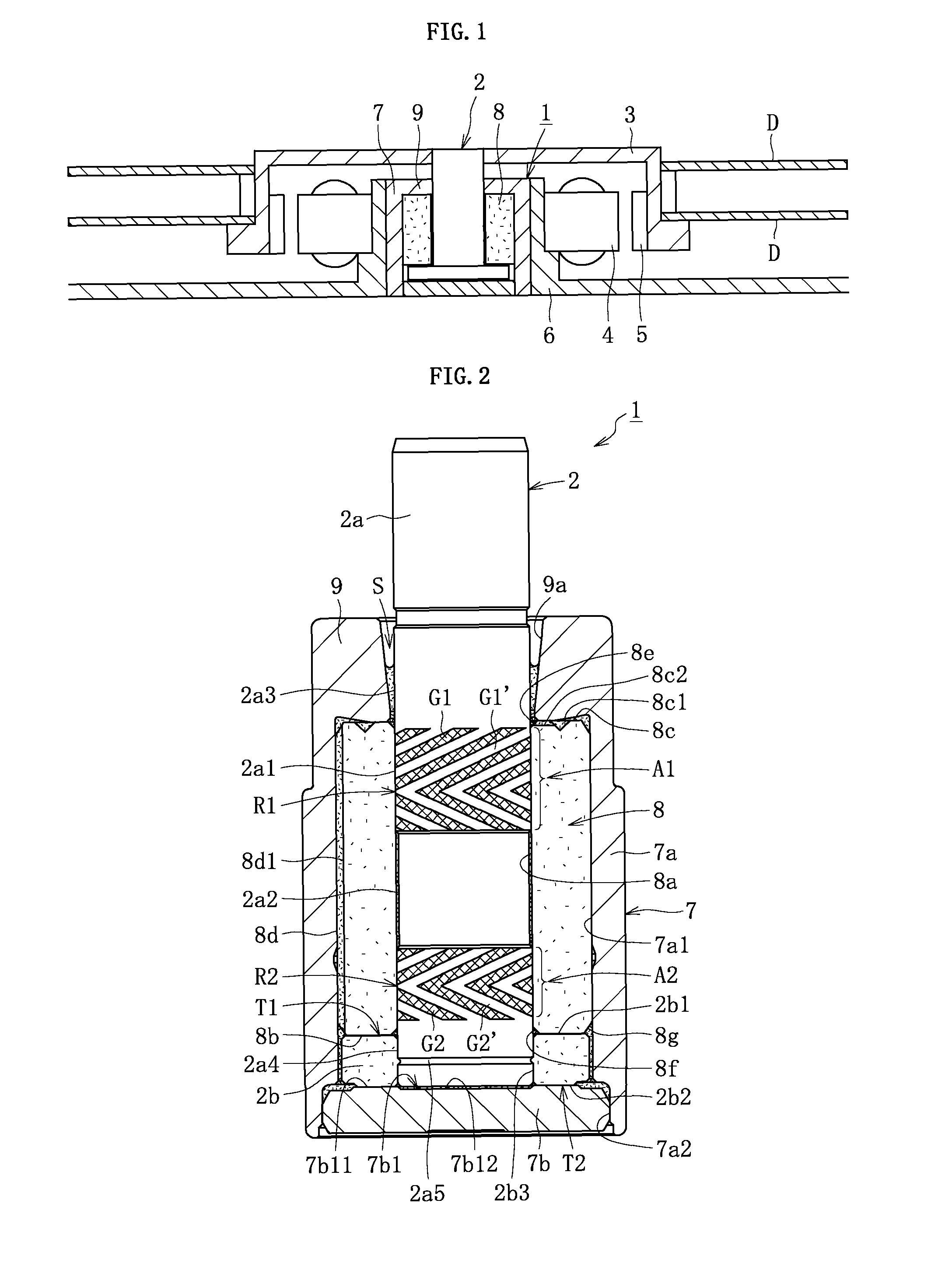
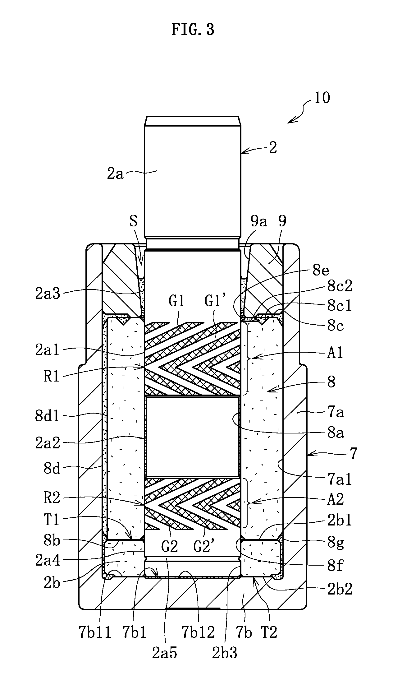
An inner peripheral surface and a lower end surface of a bearing sleeve made of a sintered metal are each formed into a smooth cylindrical surface or a flat surface that does not have a dynamic pressure generating portion. Thus, a step of forming the dynamic pressure generating portion can be omitted from a manufacturing step of the bearing sleeve, and cost of dies can be markedly reduced. Further, the inner peripheral surface of the bearing sleeve is formed into the smooth cylindrical surface, and hence a radial dynamic pressure generating portion is formed on an outer peripheral surface of a shaft member. However, the outer peripheral surface of the shaft portion is accessible to tools, and hence the radial dynamic pressure generating portion can be formed easily with high accuracy. As a result, accuracy of a radial bearing gap is enhanced so that a bearing rigidity is enhanced.

Description

CROSS-REFERENCE TO RELATED APPLICATIONS[0001]This is a 371 of International Application No. PCT / JP2012 / 054863, filed on Feb. 28, 2012, which claims the benefit of priority from the prior Japanese Patent Application Nos. 2011-050946, filed on Mar. 9, 2011, 2011-050949 filed on Mar. 9, 2011, 2011-050950 filed on Mar. 9, 2011 and 2012-012019 filed on Jan. 24, 2012 the entire contents of which are incorporated herein by reference.TECHNICAL FIELD[0002]The present invention relates to a fluid dynamic bearing device for supporting a shaft member through a dynamic pressure action of a lubricating fluid, which is generated in a radial bearing gap and a thrust bearing gap, so as to freely allow relative rotation of the shaft member.BACKGROUND ART[0003]Fluid dynamic bearing devices are excellent in rotational accuracy and quietness, and hence are suitably used, for example, in a spindle motor for various disk drive devices (such as a magnetic disk drive device for HDDs and an optical disk driv...

Claims


Application Information

Patent Timeline
Patent Type & Authority Patents(United States)
IPC IPC(8): F16C32/06F16C17/02F16C17/10F16C33/10F16C33/14F16C43/02G11B19/20
CPCF16C32/0633F16C17/026F16C43/02F16C17/107F16C33/107F16C33/14G11B19/2036F16C2220/20F16C2370/12F16C2226/52F16C2220/44F16C2240/40F16C2220/40F16C2220/70F16C2226/12F16C2223/02
Inventor NODA, HIROYUKIMORI, NATSUHIKOKURIMURA, TETSUYAKOMORI, ISAOHORI, MASAHARUBITO, KIMIHIKOMIZUTANI, TOSHIYUKI
Owner NTN CORP
Learn More