Turbine blade angel wing with pumping features

a technology of turbine blades and angel wings, which is applied in the direction of machines/engines, stators, liquid fuel engines, etc., can solve the problem that the patent appears to be limited to addressing the bow wav

Inactive Publication Date: 2015-01-06
SIEMENS AG
View PDF16 Cites 7 Cited by
  • Summary
  • Abstract
  • Description
  • Claims
  • Application Information

AI Technical Summary

Problems solved by technology

However, this patent appears to be limited to addressing the bow wave.

Method used


Image

  • Turbine blade angel wing with pumping features
  • Turbine blade angel wing with pumping features
  • Turbine blade angel wing with pumping features

Examples


Embodiment Construction

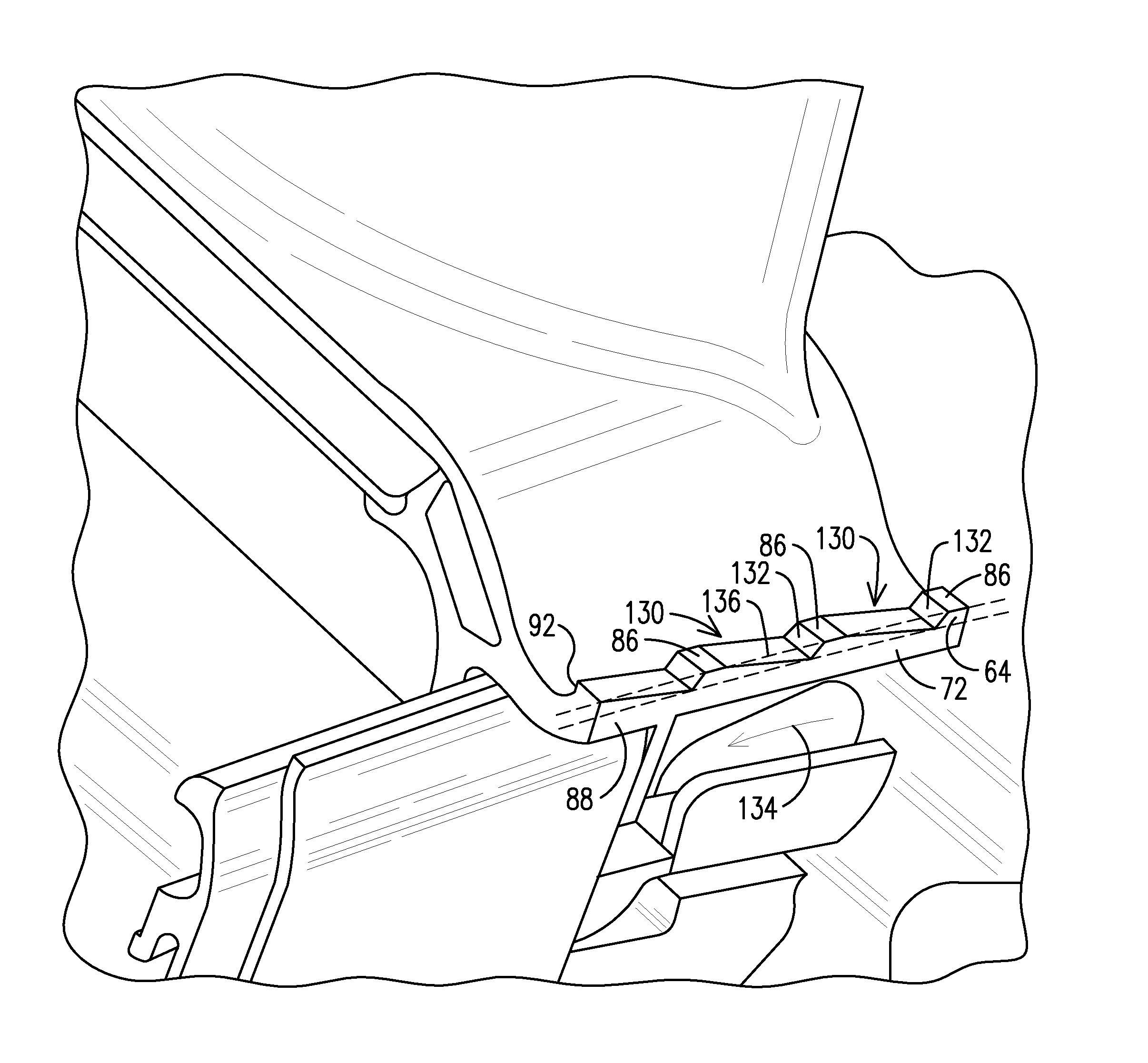
[0017]The present inventors have recognized that the aerodynamic impact of the merging of rotor purge air with the combustion gases creates vortices. These vortices tend to traverse along the suction side of the blades, from front to back and from base to tip. This causes aerodynamic losses and an associated reduction in the energy that can be extracted from the combustion gases. During operation of the gas turbine engine the rotor blades are rotating about the gas turbine engine longitudinal axis. Prior to entering the combustion gas flow, the axially flowing rotor purge air is flowing at a negative angle of incidence with respect to a leading edge of a blade. The inventors have discovered that these vortices are formed, at least in part, due to axially flowing cooling air encountering combustion gases that are flowing helically about a gas turbine engine longitudinal axis, creating a large angle of encounter. In response, the inventors have developed pumping features integral to t...


PUM


Abstract

A gas turbine engine, including: a plurality of blades (60) assembled into an annular row of blades and partly defining a hot gas path (26) and a cooling fluid path (24), wherein the cooling fluid path extends from a rotor cavity (22) to the hot gas path; an angel wing assembly (99) disposed on a side (74) of a base (76) of the row of blades; and pumping features (130) distributed about the angel wing assembly configured to impart, at a narrowest gap (42) of the cooling fluid path, motion to a flow of cooling fluid flowing there through. The plurality of pumping features, the angel wing assembly, and the base of the row of blades are effective to produce a helical motion to the flow of cooling fluid as it enters the hot gas path.

Description

FIELD OF THE INVENTION[0001]The invention relates to improving an interaction of rotor cavity purge cooling air as it enters a flow of combustion gases. In particular, the invention relates to pumping features disposed in a turbine blade angel wing that impart a swirl to the flow of cooling air.BACKGROUND OF THE INVENTION[0002]Gas turbine engines conventionally include a rotor shaft and several rows of rotor blades, each row including multiple blades distributed circumferentially about the rotor shaft. In between the rows of blades are rows of stationary vanes. Combustion gases flow along the gas turbine engine longitudinal axis in an annular flow path defined by the blades and vanes. The rotor shaft lies radially inward of the annular flow path and a rotor cavity is formed between the rotor disk and a stator structure holding the stationary vanes. Cooling air, or rotor purge air is often directed into the rotor cavity. The purge air cools components within the rotor cavity that sup...

Claims


Application Information

Patent Timeline
Patent Type & Authority Patents(United States)
IPC IPC(8): F01D11/00F01D5/14F01D11/02
CPCF01D5/141F01D5/145F01D11/001F01D11/02
Inventor LEE, CHING-PANGTHAM, KOK-MUNVITT, PAUL H.SCHROEDER, ERIC
Owner SIEMENS AG
Why Eureka
Try Eureka