Bipolar medical instrument

a medical instrument and bipolar technology, applied in the field of bipolar medical instruments, can solve the problems of leakage current, small separation of the isolating element, and remarkably reduced mechanical strength, and achieve the effects of large separation, high mechanical robustness, and avoiding voltage flashover

Active Publication Date: 2015-01-06
KARL STORZ GMBH & CO KG
View PDF26 Cites 230 Cited by
  • Summary
  • Abstract
  • Description
  • Claims
  • Application Information

AI Technical Summary

Benefits of technology

[0011]An advantage is that the first contact element which provides the current flow from the tubular shaft to the associated jaw parts is electrically isolated by the isolating element from the force transmission element. This does not only contribute to save electrical isolation between the two current paths, but the isolating element also acts as a mechanical support or mount for this first contact element. Due to fixing the first contact element at the isolating element surrounding the force transmission element, an exact positioning is given. This allows to design the second contact element very slender, sufficient to guide the current from the shaft to the respective jaw part. The force transmission occurs via the isolating element, i.e. the axial movements of the force transmission element are transferred into an axial movement of the first contact element fixed thereon.
[0031]This has the advantage that the electrically isolating elements made from this material can be particularly highly mechanically robust, thus ensuring the whole function that is to save force transmission on the one hand and isolation on the other hand in the long term.

Problems solved by technology

The electrical isolation of the two jaw parts from one another in the area of the joint has the problem that, particularly in the case of thin instruments, these isolating elements are very small and their mechanical strength is remarkably reduced.
In use, the jaw parts come into contact with electrically conductive liquids, in particular with body fluids, which can result in creepage currents via the isolating elements, thus leading to shorts.
During use and in contact with electrically conductive liquids like body liquids, leakage currents can result between these two contact elements of different polarity.

Method used


Image

  • Bipolar medical instrument
  • Bipolar medical instrument
  • Bipolar medical instrument

Examples


Embodiment Construction

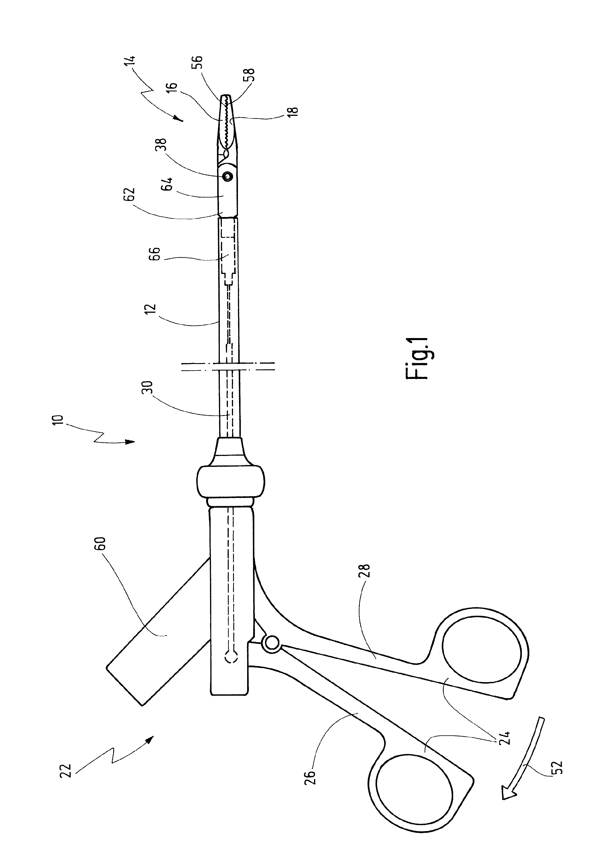
[0041]A bipolar medical instrument as illustrated in FIG. 1 is annotated with the reference number 10 in its totality. The instrument 10 is used for minimal-invasive surgical interventions for the treatment of tissue in human or animal bodies, for preparation by means of high-frequency current.

[0042]The exemplary embodiment of the instrument 10 illustrated in FIG. 1 is a gripping instrument or gripping tongs.

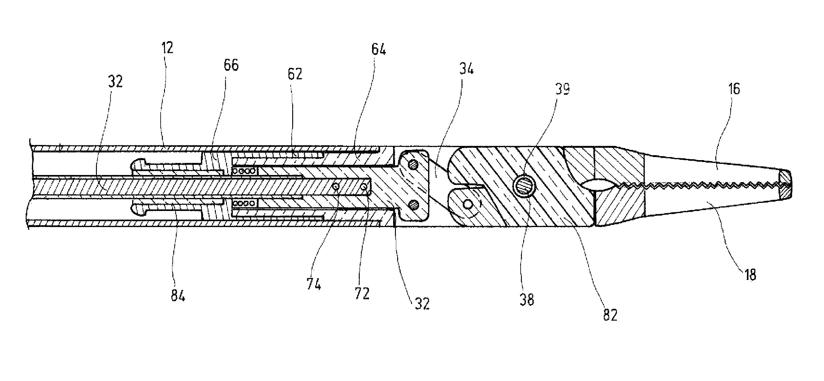
[0043]The instrument 10 has an elongated tubular shaft 12. The tubular shaft 12 is formed from an electrically conductive material, preferably from metal.

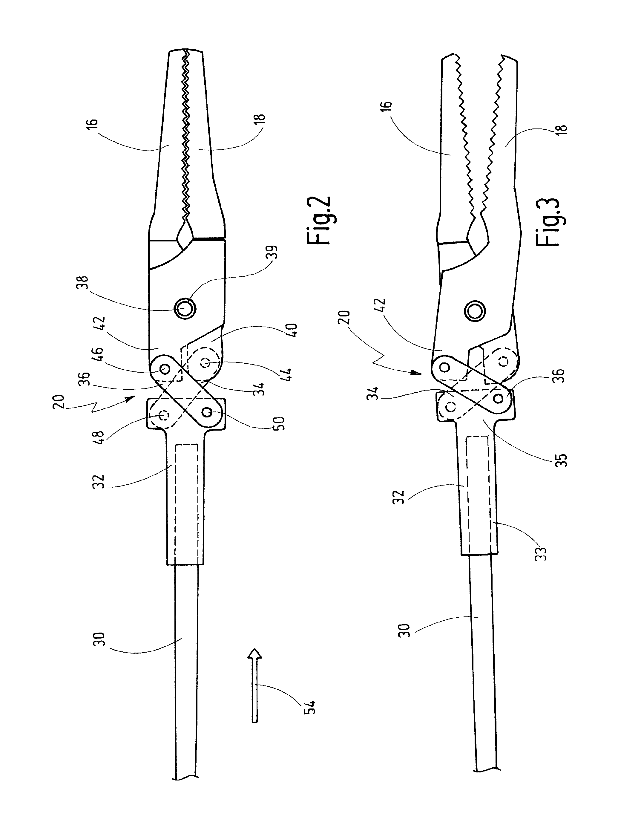
[0044]Two jaw parts 16, 18 are arranged at a distal end 14 of the tubular shaft 12. The jaw parts 16, 18 are connected to one another via an articulation pivot 38 and can move relative to one another, as will also be described later in conjunction with FIGS. 2 and 3.

[0045]A housing 62 is provided at the distal end area of the instrument 10. A distal fork-head-like area 64 of the housing 62 is formed from an electrically insulat...


PUM


Abstract

A bipolar medical instrument has a shaft and two jaw parts arranged at the distal end thereof. An axially movable force transmission element is disposed with the shaft and is surrounded by an isolating element. The isolating element is connected to at least one of the two jaw parts in an articulated manner. The two jaw parts are electrically isolated from one another and each provides an electrode to which high frequency current can be applied. A first electrical supply line is formed along the shaft via an electrically conductive first contact element to one of the two jaw parts. A second electrical supply line is formed along the axially movable force transmission element via an electrically conductive second contact element to the other of the two jaw parts. The first contact element is fixed at the isolating element surrounding the distal end area of the force transmission element.

Description

BACKGROUND OF THE INVENTION[0001]The invention relates to a bipolar medical instrument.[0002]Bipolar medical instruments are used to thermally cut, to coagulate or to cut and to coagulate tissue in a human or animal body under the influence of bipolar high-frequency current.[0003]Bipolar instruments usually have a tubular shaft at whose distal end two jaw parts which are connected to one another in an articulated manner are arranged and can move relative to one another. A force transmission element which can move axially is arranged in the tubular shaft and is connected such that force can transmitted from a handle arranged at a proximal end to at least one jaw part, specifically the moving jaw part arranged at the distal end of the shaft. The jaw parts can be opened and closed by operation of the handle. The jaw parts each form an electrode, to which high-frequency current can be applied and which is of different polarity. Each jaw part has a separate associated electrical power su...

Claims


Application Information

Patent Timeline
Patent Type & Authority Patents(United States)
IPC IPC(8): A61B18/14
CPCA61B18/1445
Inventor BACHER, UWEBLOCHER, MARTINWEINMANN, DANIEL
Owner KARL STORZ GMBH & CO KG
Why Eureka
Try Eureka