Thermal stress reduction

a technology of thermal stress and reduction of stress, which is applied in the direction of semiconductor devices, semiconductor/solid-state device details, capacitors, etc., can solve the problems of warping and less manageable wafers, high cost, and breakage of wafers

Active Publication Date: 2015-01-06
NXP BV
View PDF13 Cites 1 Cited by
  • Summary
  • Abstract
  • Description
  • Claims
  • Application Information

AI Technical Summary

Benefits of technology

[0022]The forming of the holes is preferably combined with other processing steps or another step to avoid additional operations and manipulations prior to, or after standard wafer processing, and it therefore optimizes fabrication quality and costs.
[0040]It is noted that the present invention further provides advantages when actually sawing the wafer. Due to the dotted grooves it becomes easier to saw the dies.

Problems solved by technology

It can cause wafers to become warped and less manageable, and in worst cases it can even cause breakage of wafers.
Therefore the cost involved is quite high, especially in view of the small number of holes that are formed.
Clearly the time involved for etching is quite long, which makes the process unfavorable, also in terms of costs allocated to use of equipment, chemicals, and environmental and health risks.
Furthermore, even wafers comprising plural sets of through holes suffer from warpage, albeit at a lower extend.
Further, performing a plasma treatment on a finished wafer, if not perfectly controlled, could damage adjacent sensitive structures on the integrated circuits
A disadvantage hereof is that the necessity to interrupt grooves in the alignment pattern regions exists.
Further, stress reduction is less effective when a groove does not run all over the wafer.
This method is regarded as being expensive and rather complicated.

Method used


Image

  • Thermal stress reduction
  • Thermal stress reduction
  • Thermal stress reduction

Examples


Embodiment Construction

[0016]In a first embodiment the invention relates to a method for thermal stress reduction on a wafer, comprising the steps of:

[0017]providing a wafer with an alignment pattern and saw lanes between adjacent dies,

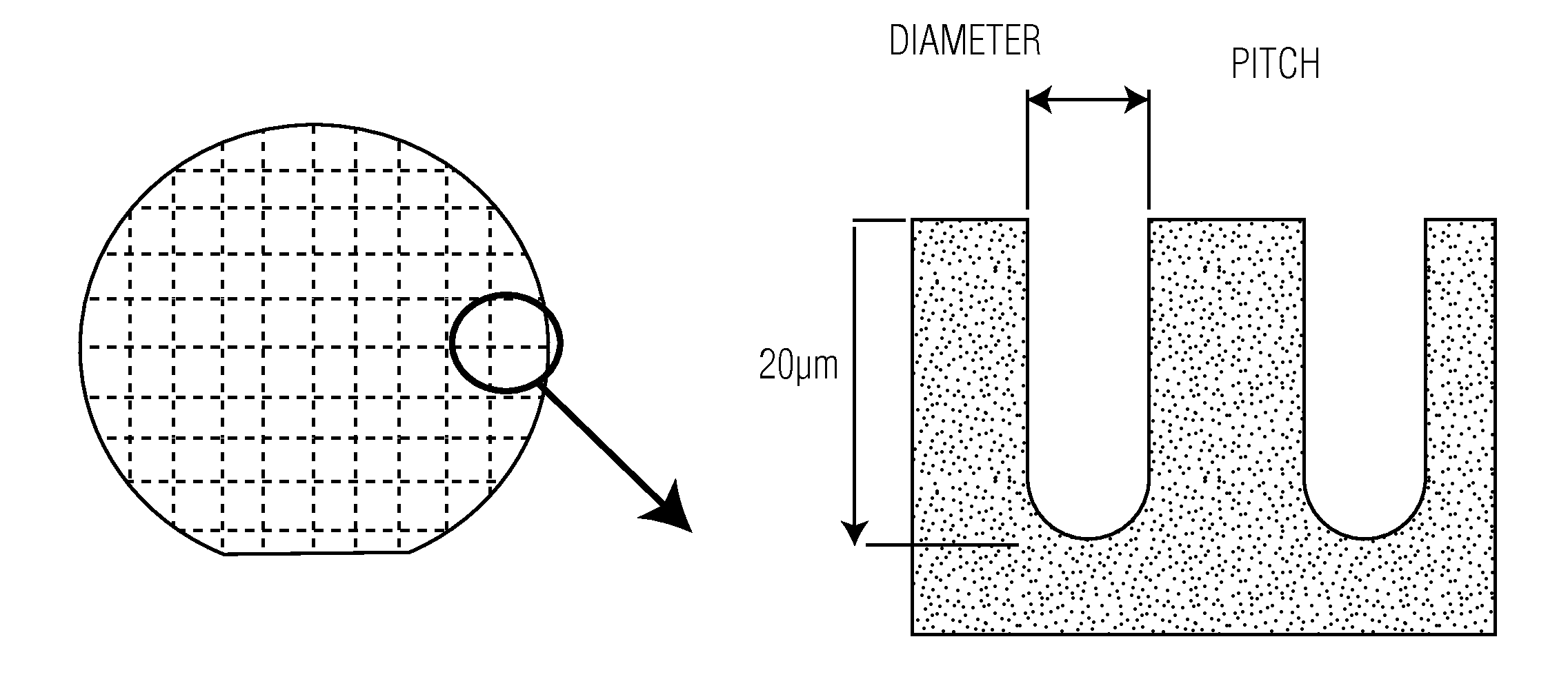
[0018]forming thin holes within the silicon substrate, which holes create a dotted groove in the saw lanes, wherein no second layer on an opposing side of the wafer is formed.

[0019]In order to be able to define dies on a wafer, an alignment pattern for lithographic equipment needs to be present.

[0020]Whenever the term “saw lanes” is used, it also refers to scribe lanes or scribe lines.

[0021]Further, it is not necessary that the saw lanes have already been physically defined on the wafer. Actually, and preferably, the saw lanes may also be virtually present, that is, the holes which are formed by the present method, are formed at locations, where in subsequent process steps the saw lanes are formed. As such, the holes would be present “underneath” saw lanes, that is in a ver...


PUM


Abstract

The present invention relates to a method for thermal stress reduction on a wafer, comprising the steps of providing a patterned wafer with saw lanes between adjacent dies, forming thin holes within the silicon substrate, which holes create a dotted groove in the saw lanes, and wherein no second layer on an opposing side of the wafer is formed, a patterned wafer obtained by said method. The forming of the holes is preferably combined with other processing steps or another step to avoid additional operations and manipulations prior to, or after standard wafer processing, and it therefore optimizes fabrication quality and costs. Preferably the holes within the silicon substrate having a depth of more than 3 to 50 μm, preferably from 5-40 μm, like 20 μm.

Description

FIELD OF THE INVENTION[0001]This invention relates to thermal stress reduction on a wafer and a wafer with reduced thermal stress.BACKGROUND OF THE INVENTION[0002]Stress is a constant presence in the semiconductors manufacturing. It can cause wafers to become warped and less manageable, and in worst cases it can even cause breakage of wafers.[0003]Methods of reducing thermal stress are disclosed in the prior art.[0004]JP 02-181425 discloses plural sets of pinhole shaped through holes, which are made in advance. These holes are formed in scribe lanes on the wafer. Thereto an etch process is used.[0005]However, an etch process, such as a RIE process, provides for a speed of 1 to 10 μm per minute, on a wafer that typically is 300 to 400 μm thick. Therefore the cost involved is quite high, especially in view of the small number of holes that are formed.[0006]Clearly the time involved for etching is quite long, which makes the process unfavorable, also in terms of costs allocated to use ...

Claims


Application Information

Patent Timeline
Patent Type & Authority Patents(United States)
IPC IPC(8): H01L29/72H01L21/02H01L21/78H01L23/544H01L49/02
CPCH01L23/544H01L21/02005H01L21/78H01L28/90H01L2223/54426H01L2223/5446H01L2924/0002H01L2924/00
Inventor COUSIN, ALAIN
Owner NXP BV
Why Eureka
Try Eureka