[0029]According to the tongue of the present invention having such a structure, a predetermined number of the concave portions are provided in the seat belt sliding surface, and a predetermined number of the protrusions are provided in the concave portions. In this manner, since, at normal times, a tension force exerted on the seat belt is low, the seat belt is not in contact with the protrusions. Alternatively, even when the seat belt is in contact with any one of the protrusions, the seat belt is in low force contact with the protrusion. Accordingly, the seat belt actually slides on the seat belt sliding surface. Thus, at normal times, the seat belt can smoothly slide on the tongue. As a result, the operability of the seat belt can be effectively improved at normal times. In contrast, in the event of an emergency, the tension force exerted on the seat belt significantly increases. At that time, the seat belt enters the concave portions, and the protrusions bite into the seat belt. Accordingly, even when the seat belt attempts to stretch toward the lap belt, movement of the seat belt toward the lap belt can be effectively stopped due to the gripping forces (the frictional forces) of the protrusions against the seat belt. As a result, stretch of the lap belt occurring in the event of an emergency can be effectively prevented, and the occupant can be more effectively restrained by the lap belt.
[0030]In particular, each of the protrusions is formed in the concave portion so as not to protrude outwardly beyond the seat belt sliding surface. Accordingly, at normal times, the seat belt can more effectively smoothly slide on the tongue.
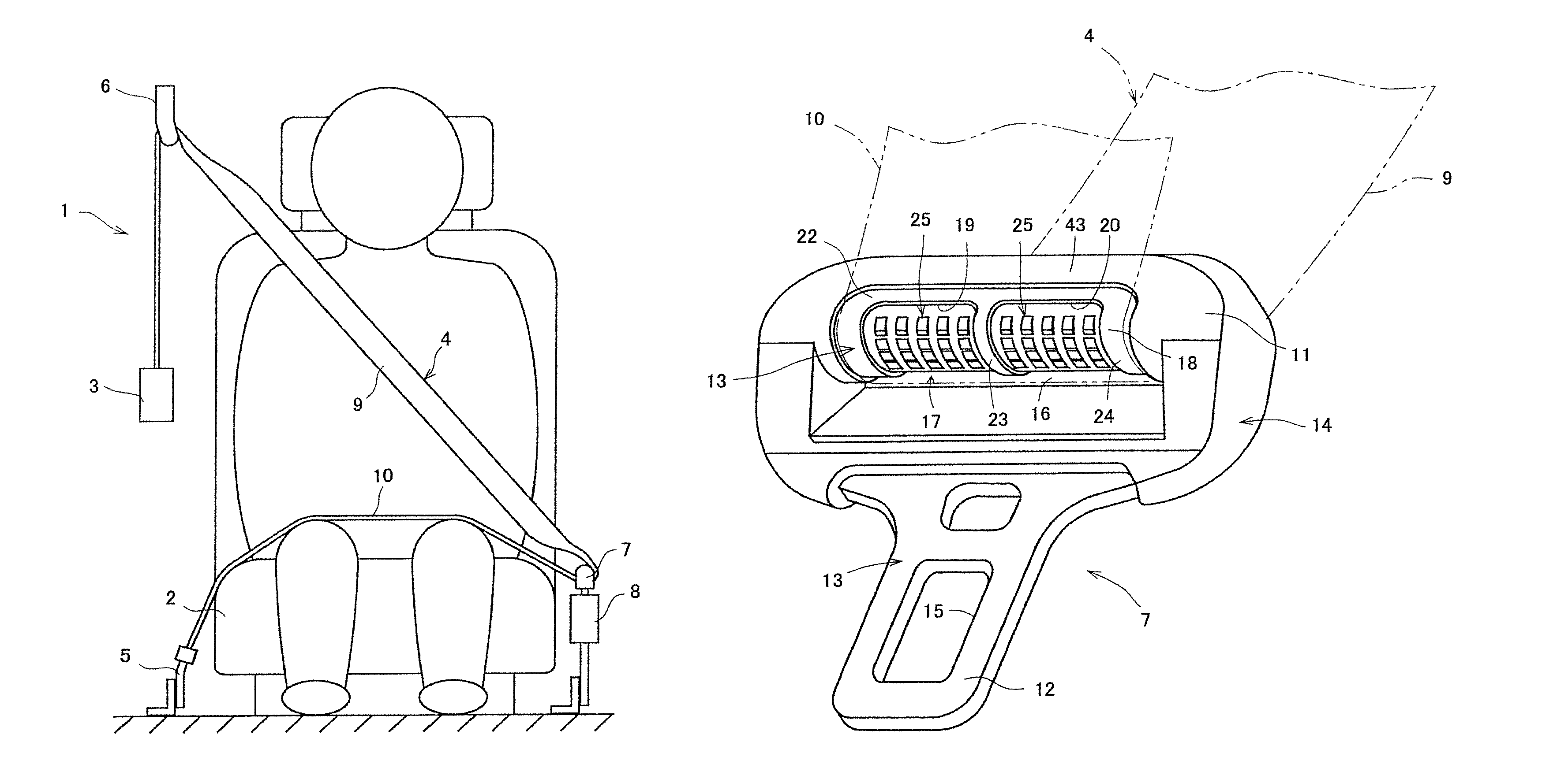
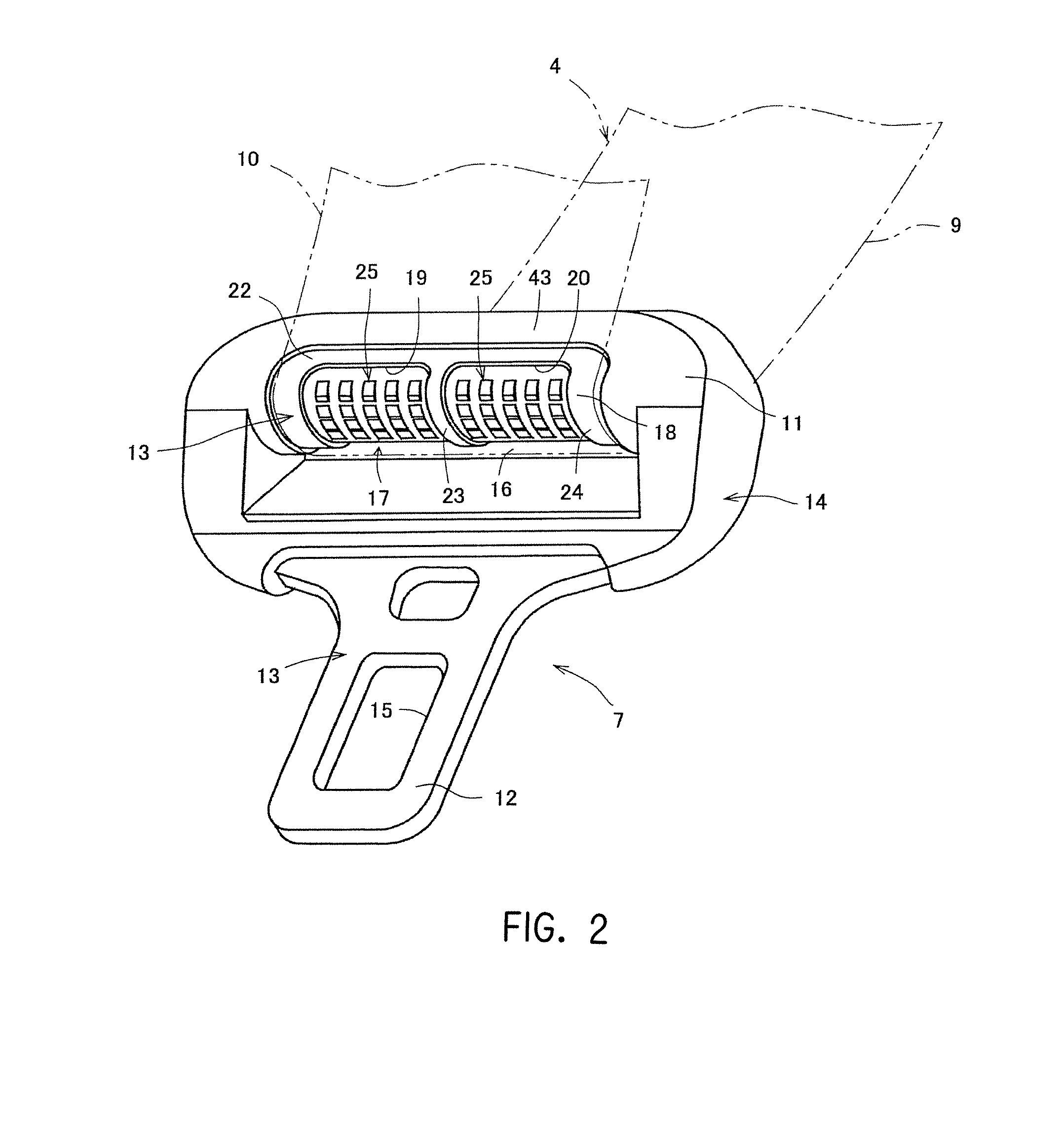
[0031]In addition, the cross section of each of the predetermined number of the protrusions in a direction perpendicular or substantially perpendicular to the seat belt insertion hole is formed in a triangular shape including a flat or substantially flat end surface on the shoulder belt side and a flat or substantially flat end surface on the lap belt side. Furthermore, an angle formed by the seat belt in slide contact with at least some of the protrusions and the end surface on the shoulder belt side is set to a relatively large value, and an angle formed by the seat belt and the end surface on the lap belt side is set to a relatively small value. Accordingly, when the seat belt is worn in the event of an emergency and if the seat belt in slide contact with at least some of the protrusions attempts to move toward the lap belt, the gripping force (the frictional force) of at least some of the protrusions can be relatively increased. Thus, stretch of the lap belt can be effectively prevented. In addition, when the seat belt is worn and if the seat belt in slide contact with at least some of the protrusions attempts to move toward the shoulder belt, the gripping force (the frictional force) of at least some of the protrusions can be relatively decreased. Thus, the seat belt can relatively smoothly move toward the shoulder belt. In addition, since the top end of each of the protrusion is formed as a circular arc having a predetermined radius of curvature (an R portion), the strength of the seat belt can be maintained so as to support a relatively large force exerted from the protrusions onto the seat belt in the event of an emergency.
[0032]Furthermore, the shoulder belt side seat belt sliding surface disposed along in the length direction of the seat belt insertion hole extends from a shoulder belt side of a position at which a distance in a direction perpendicular or substantially perpendicular to the length direction of the seat belt insertion hole is minimized to a lap belt side of the position, and a portion of the shoulder belt side seat belt sliding surface is located on the lap belt side of the position at which the distance is minimized. In this manner, even when the concave portions are provided in the seat belt sliding surface, the seat belt can be caused to pass through the smooth minimum width portion of the seat belt insertion hole where the concave portions are not located. Thus, turnover of the seat belt can be prevented, and the seat belt can be maintained untwisted. In this manner, at normal times, the seat belt can easily and smoothly slide on the tongue, and the operability of the seat belt can be more improved at normal times.
[0033]Still furthermore, by forming the cross section of the outer peripheral surface of the concave portion formed in the seat belt sliding surface in a direction perpendicular or substantially perpendicular to the length direction of the seat belt insertion hole in an arc shape, the seat belt can more effectively slide on the tongue at normal times. In addition, in the event of an emergency, the lap belt can more effectively restrain the occupant.
[0034]Still furthermore, the seat belt sliding surface includes the first and second end seat belt sliding surfaces at either end thereof in the length direction of the seat belt insertion hole. The first and second end seat belt sliding surfaces extend in a direction that is perpendicular or substantially perpendicular to the length direction of the seat belt insertion hole. In addition, a plurality of the concave portions are provided, and the seat belt sliding surface includes the intermediate seat belt sliding surface between the concave portions. The intermediate seat belt sliding surface extends in the direction that is perpendicular or substantially perpendicular to the length direction of the seat belt insertion hole. In this manner, at normal times, the seat belt can easily and smoothly slide on the tongue, and the operability of the seat belt at normal times can be more improved.

