Print control apparatus, printing system, and print control method

Inactive Publication Date: 2015-01-13
RICOH KK
View PDF31 Cites 4 Cited by
  • Summary
  • Abstract
  • Description
  • Claims
  • Application Information

AI Technical Summary

Problems solved by technology

There has been a known technology for obtaining gloss by using the clear toner in a region that is not glossy because toner is non-uniformly attached to the region.
Therefore, the primary color image and the corporate logo often overlap each other at some portions, where a conflict occurs between the above-mentioned two types of methods of using the clear toner.

Method used


Image

  • Print control apparatus, printing system, and print control method
  • Print control apparatus, printing system, and print control method
  • Print control apparatus, printing system, and print control method

Examples


first embodiment

[0068

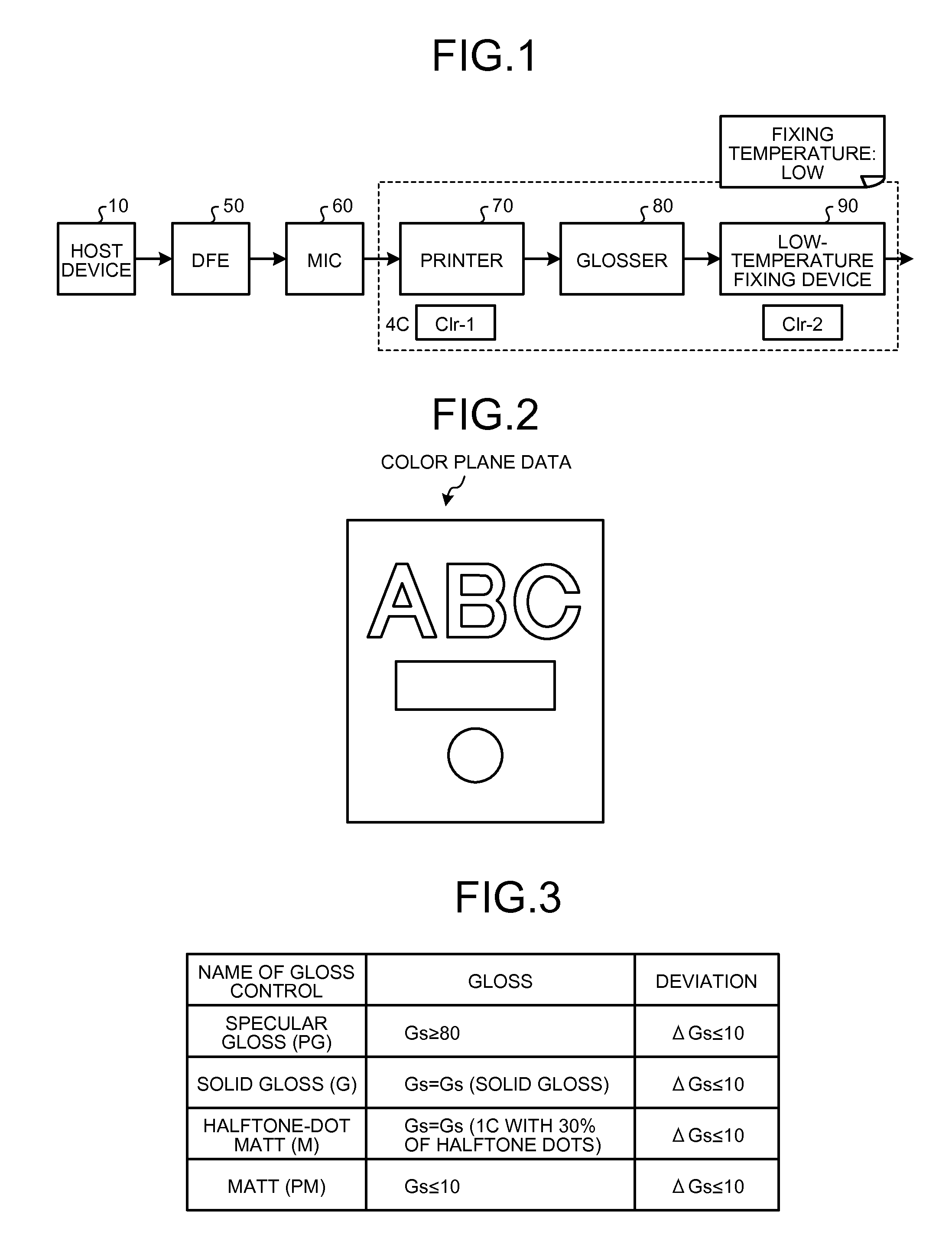
[0069]A configuration of an image forming system according to a first embodiment will be explained below with reference to FIG. 1. In the present embodiment, the image forming system includes a printer control device (a Digital Front End (DFE)) 50 (hereinafter, described as “the DFE 50”), an interface controller (Mechanism I / F controller (MIC)) 60 (hereinafter, described as “the MIC 60”), a printer 70, a glosser 80 as a post processing device, and a low-temperature fixing device 90 as a post processing device, which are connected to one another. The DFE 50 communicates with the printer 70 via the MIC 60 and controls image formation performed by the printer 70. The DFE 50 is connected to a host device 10, such as a personal computer (PC); receives image data from the host device 10; generates image data, which is to be used by the printer 70 to form toner images corresponding to CMYK toners and a clear toner, by using the received image data; and sends the image data to the prin...

second embodiment

[0171

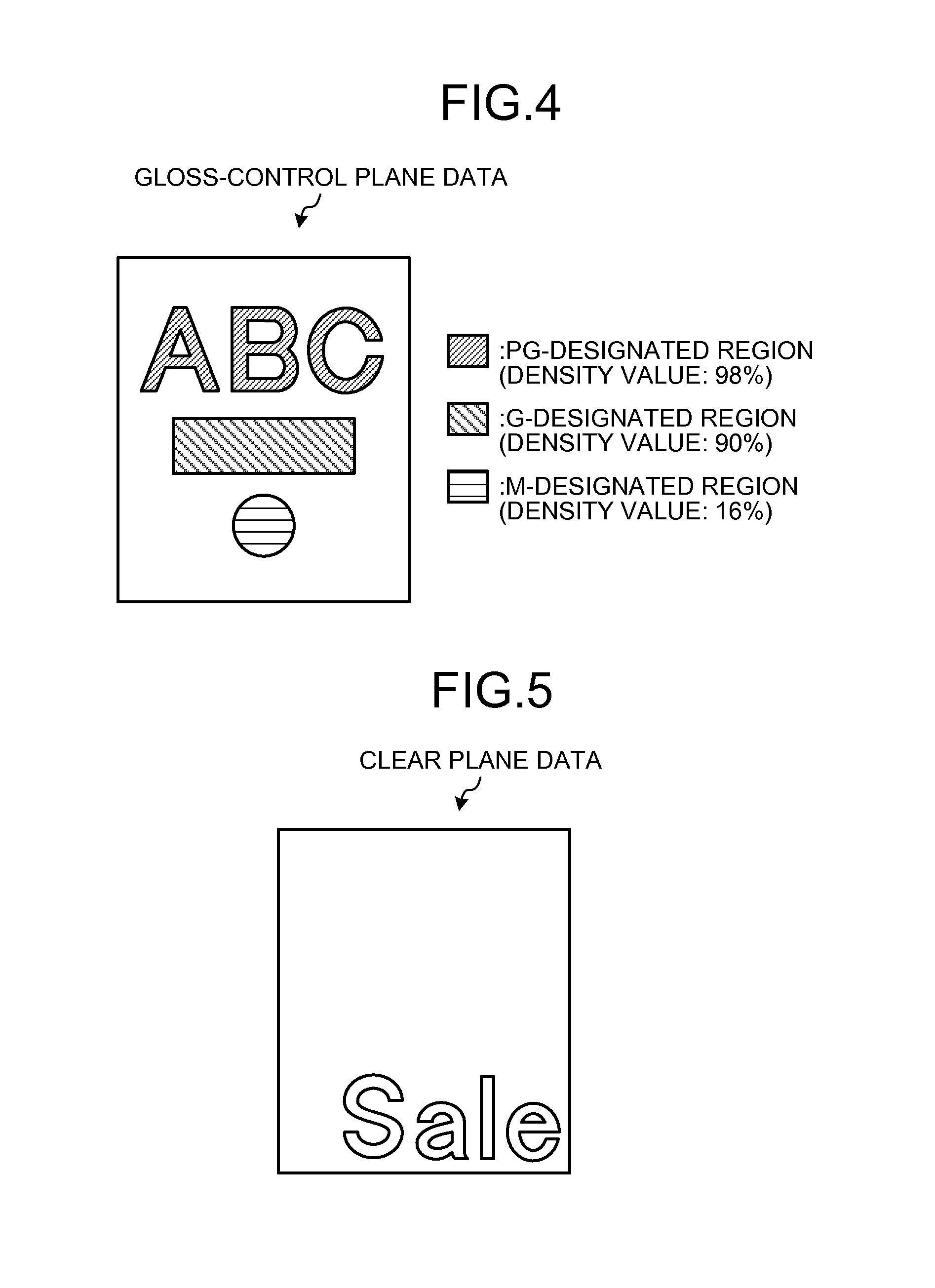
[0172]In the first embodiment, the clear-toner plane data is set to have a pixel value of either the clear plane data or the gloss-control plane data, based on the plane priority information indicating whether priority is given to the clear plane data or the gloss-control plane data, with respect to the overlapping area in which a region where the transparent image, such as a watermark, is specified in the clear plane data and a region where the surface effect is specified in the gloss-control plane data overlap each other. In the second embodiment, a plurality of patterns indicating different priority orders of a plurality of types of the surface effects and the transparent image are registered as the plane priority information; a priority order specified by a user is acquired as the plane priority information; and the clear-toner plane data is set to have a pixel value of either the clear plane data or the gloss-control plane data.

[0173]In the host device 10 of the present em...

third embodiment

[0187

[0188]In the first embodiment, the clear-toner plane data is set to have a pixel value of either the clear plane data or the gloss-control plane data, based on the plane priority information indicating whether priority is given to the clear plane data or the gloss-control plane data, with respect to the overlapping area in which a region where the transparent image, such as a watermark, is specified in the clear plane data and a region where the surface effect is specified in the gloss-control plane data overlap each other. In the third embodiment, a user is allowed to specify whether to give priority to the clear plane data or the gloss-control plane data for each region, and a pixel value of the clear-toner plane data is set to a pixel value of the plane data that is specified in the plane priority information for each region in the overlapping area.

[0189]In the host device 10 of the present embodiment, the display control unit 121 displays a screen for allowing a user to spe...


PUM


Abstract

A print control apparatus includes a generating unit that generates clear-toner plane data based on gloss-control plane data, which contains a gloss control value for specifying a type of a surface effect being a visual or a tactile effect applied to the recording medium and for specifying a region to which the surface effect is applied in the recording medium, and clear plane data, which contains a density value for specifying a transparent image other than the surface effect; and an outputting unit that outputs the clear-toner plane data. When a region where the gloss control value is specified in the gloss-control plane data and a region where the density value is specified in the clear plane data overlap each other, the generating unit sets a value of the clear-toner plane data to the gloss control value or the density value, based on a predetermined condition.

Description

CROSS-REFERENCE TO RELATED APPLICATIONS[0001]The present application claims priority to and incorporates by reference the entire contents of Japanese Patent Application No. 2011-061511 filed in Japan on Mar. 18, 2011 and Japanese Patent Application No. 2012-056467 filed in Japan on Mar. 13, 2012.BACKGROUND OF THE INVENTION[0002]1. Field of the Invention[0003]The present invention relates to a print control apparatus, a printing system, and a print control method.[0004]2. Description of the Related Art[0005]There has been a known printing method, in which a color image as a target image of color printing is formed with color toners of C (cyan), M (magenta), Y (yellow), and K (black) and a corporate logo etc. is superimposed on the target color image such that the logo etc. does not influence the target color image nor stand out. To prevent the superimposed logo etc. from standing out, printing is performed by using a clear toner that is colorless and transparent and adding gloss so t...

Claims


Application Information

Patent Timeline
Patent Type & Authority Patents(United States)
IPC IPC(8): G03G15/20G03G15/00
CPCG03G15/50G03G15/6585
Inventor YOSHIKAWA, TAKASHISUZUKI, HIROAKIKITAGAWA, HIROO
Owner RICOH KK
Why Eureka
Try Eureka