Duct detector with improved functional test capability

a duct detector and functional testing technology, applied in the field of air handling systems, can solve the problems of high inconvenient and even hazardous functional testing tasks, duct detector performance can degrade over time, and achieve the effect of convenient functional testing of the duct detector

Active Publication Date: 2015-01-27
JOHNSON CONTROLS TYCO IP HLDG LLP
View PDF14 Cites 1 Cited by
  • Summary
  • Abstract
  • Description
  • Claims
  • Application Information

AI Technical Summary

Benefits of technology

[0013]The above-described duct detector and test method thus facilitate convenient functional testing of the duct detector without requiring an individual to access a hard-to-reach, potentially hazardous location or introduce foreign particulate into a duct system.

Problems solved by technology

It is known that performance of duct detectors can degrade over time due to reasons such as electrical failure or particulate clogging of a detector's filter screen.
A problem commonly associated with testing the functionality of duct detectors in the manner described above is that duct detectors are often installed in elevated locations, sometimes above ceilings, with few surrounding structures capable of supporting the weight of an individual during testing.
Detectors that are located in such areas offer poor accessibility, rendering the task of functional testing highly inconvenient and even hazardous.
If, upon activation of the test light, the control circuitry does not receive an output signal from the light detector that exceeds the trip level, the control circuitry will not generate the alarm signal and it can therefore be determined that the duct detector is not functioning properly.

Method used


Image

  • Duct detector with improved functional test capability
  • Duct detector with improved functional test capability
  • Duct detector with improved functional test capability

Examples


Embodiment Construction

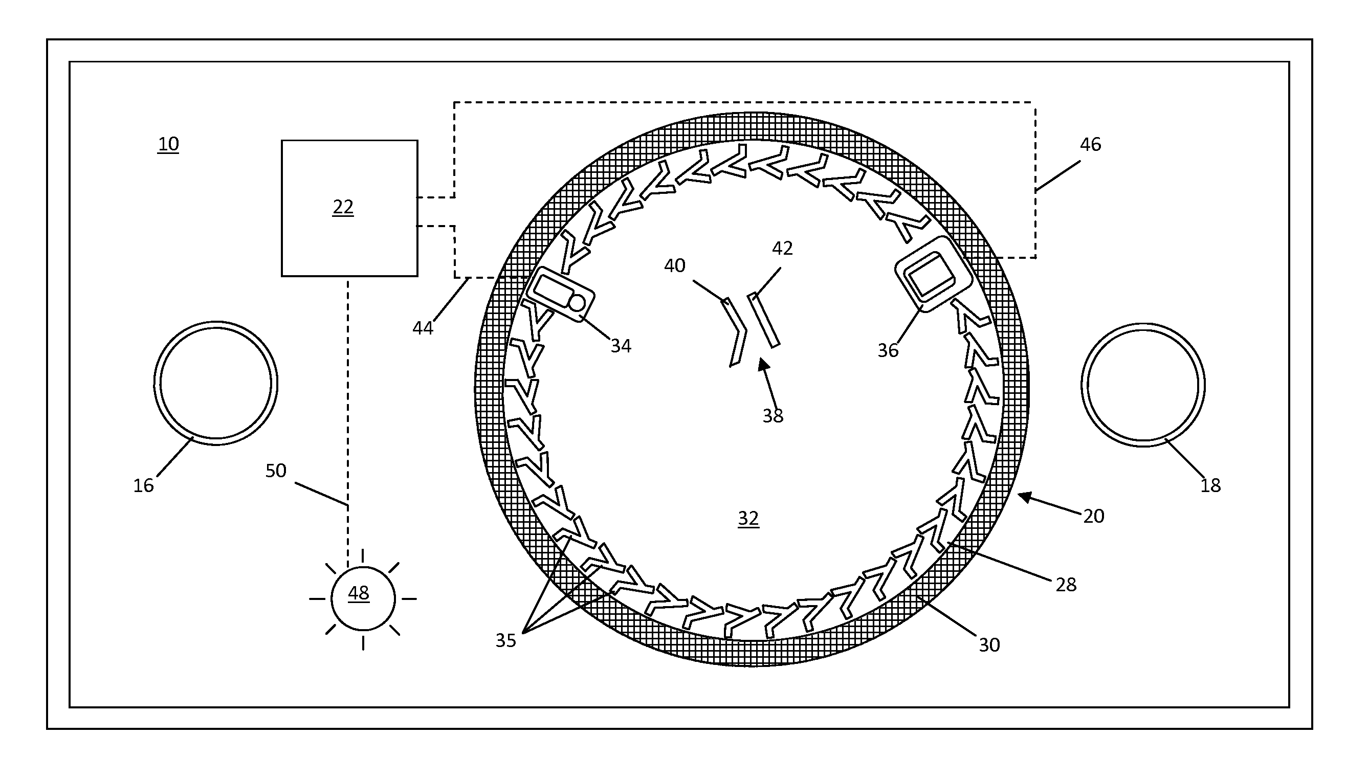
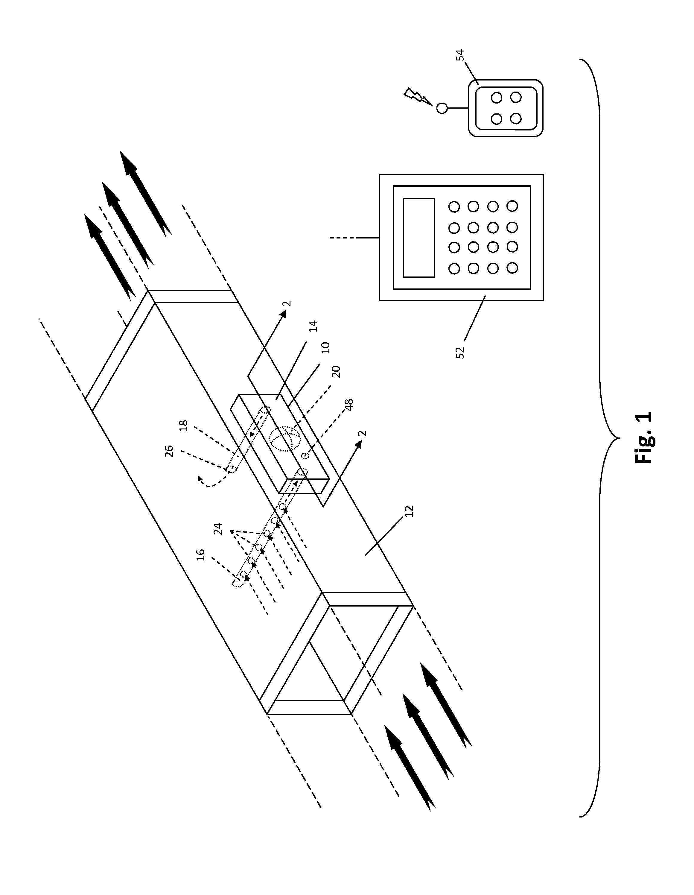
[0019]Referring to FIG. 1, an improved duct detector 10 for facilitating convenient functional testing thereof is shown operatively installed on a section of duct 12. It is to be understood that the particular duct 12 is shown by way of example only, and is meant to be representative of any type of duct, such as may be commonly found in a variety of different buildings, and that the duct detector 10 can be employed in the manner described below in numerous other duct configurations. For example, the size and shape of the duct 12 can be varied with little or no effect on the functionality of the duct detector 10.

[0020]For the sake of convenience and clarity, terms such as “front,”“rear,”“top,”“bottom,”“upstream,”“downstream,”“inwardly,” and “outwardly,” will be used herein to describe the relative placement and orientation of the duct detector 10 and its various components, all with respect to the geometry and orientation of the duct detector 10 as it appears in FIG. 1. Particularly,...


PUM

PropertyMeasurementUnit
output voltageaaaaaaaaaa
threshold voltageaaaaaaaaaa
output voltageaaaaaaaaaa

Abstract

A device and method for facilitating convenient functional testing of a duct detector is provided. The device includes a duct detector having a remote-controlled test light mounted in a housing thereof, and a detector chamber defined by a filter screen and a plurality of labyrinth members that allow light emitted by the test light to enter the detector chamber. A functional test of the duct detector can be conducted by activating the test light. If the detector is functioning properly, an amount of light emitted by the test light will be detected by the light detector, thereby simulating the presence of an excessive amount of particulate within the detector chamber. The light detector will then generate an output signal that will cause the actuation of alarms and / or the deactivation of a blower system, thereby indicating functionality of the duct detector.

Description

FIELD OF THE DISCLOSURE[0001]The disclosure relates generally to air handling systems, and more particularly to a device and method for facilitating convenient functional testing of a duct detector.BACKGROUND OF THE DISCLOSURE[0002]Air handling systems, such as heating, ventilation, and air conditioning (HVAC) systems, are an important feature of modern building infrastructure. It is often critical that air which flows though air handling systems be continuously monitored for the presence of impurities that may pose a threat to the health and well-being of a building's occupants. For example, it is common to monitor the levels of oxygen, carbon monoxide, particulate, and smoke in air that flows through a building's air handling system. Such monitoring is typically facilitated by duct detectors that are installed at various locations throughout a building's ductwork.[0003]Unlike conventional smoke detectors and other so-called “point detectors” that are commonly mounted to ceilings o...

Claims


Application Information

Patent Timeline
Patent Type & Authority Patents(United States)
IPC IPC(8): G08B17/10G08B17/103G08B17/107G01N21/53G08B17/12
CPCG01N21/4738G01N21/53G08B17/107G08B29/145G08B17/113
Inventor BRIGHENTI, DONALD D.BROOKS, JEFFREY R.
Owner JOHNSON CONTROLS TYCO IP HLDG LLP
Why Eureka
Try Eureka