
Fog removal system

a fog removal and fog technology, applied in the field of fog removal, can solve the problems of reducing visibility, hindering safe operations, and causing fog to occur, so as to prevent accidents, minimize casualties, and actively remove fog

Inactive Publication Date: 2015-01-27
KOREA MAINTENANCE & CONTROL +1
View PDF10 Cites 1 Cited by
  • Summary
  • Abstract
  • Description
  • Claims
  • Application Information

AI Technical Summary

Benefits of technology

The present invention is a fog removal system that can be installed in areas where fog often occurs, such as roads, airports, and harbors. The system uses a strong blowing pressure to reduce the humidity in the area and remove fog. By applying the system to a road, it can prevent accidents and minimize casualties caused by fog. Additionally, the invention includes an illuminance-detecting sensor that can detect fog based on its unique illuminance levels. This technology is effective and efficient in preventing accidents and minimizing casualties caused by fog.

Problems solved by technology

When air cools under these conditions, fog occurs.
Fog, a natural phenomenon resulting from a rapidly changing temperature, greatly reduces visibility, thereby substantially hindering safe operations.
That is, a pilot who operates an airplane may not secure a sufficient visual range in thick fog so that the airplane may not safely take off or land.
In particular, when the airplane is to land and thick fog occurs over an airplane runway, since the pilot has to take the airplane to another airport, passengers may feel discomfort and an airline may suffer huge losses.
Also, there are areas in which fog regularly occurs along highways on which cars travel.
Fog is one of the most dangerous factors in blocking visibility of drivers on roads.
The frequency of accidents due to fog that hinders safe operations is actually high, and the risk of chain collisions may increase due to fog.
However, since these methods greatly reduce driving speeds of cars and thereby obstruct smooth traffic flow and cause traffic jams, economic losses are incurred.
Also, since these methods do not fundamentally remove fog, similar accidents repeatedly occur in areas in which fog regularly occurs, thereby leading to mass casualties.
In fact, however, the barrier walls may physically block fog but do not remove fog.
As a result, since fog traveling along the ground rises and falls along the barrier walls and enters onto the road, it is difficult to expect that the barrier walls may block fog and thus prevent various accidents due to fog on the road, and costs of installing the barrier walls are high.

Method used


Image

  • Fog removal system
  • Fog removal system
  • Fog removal system

Examples


Embodiment Construction

[0027]The present invention can remove fog by blowing dry air onto areas such as roads, airport runways, harbors, or coastal areas in which fog regularly occurs, to reduce a relative humidity of 100% of wet atmospheric air. When applied to a road, the fog removal system may be installed in a longitudinal direction of the road, spaced a predetermined distance apart on both sides of inbound and outbound lanes of the road, to remove fog by using dry air and form an air curtain by using the dry air blown from both sides of the road to block advection fog introduced from the outside by using the air curtain. Thus, a visual range of drivers can be secured along the road. The present invention will be explained in detail with reference to the attached drawings.

MODES OF THE INVENTION

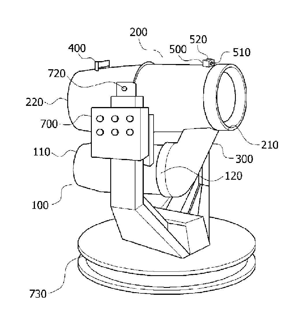
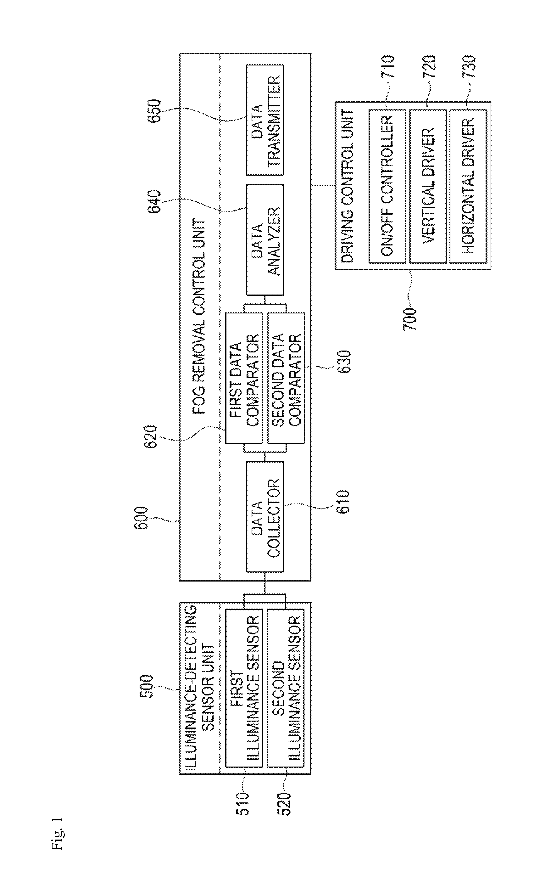
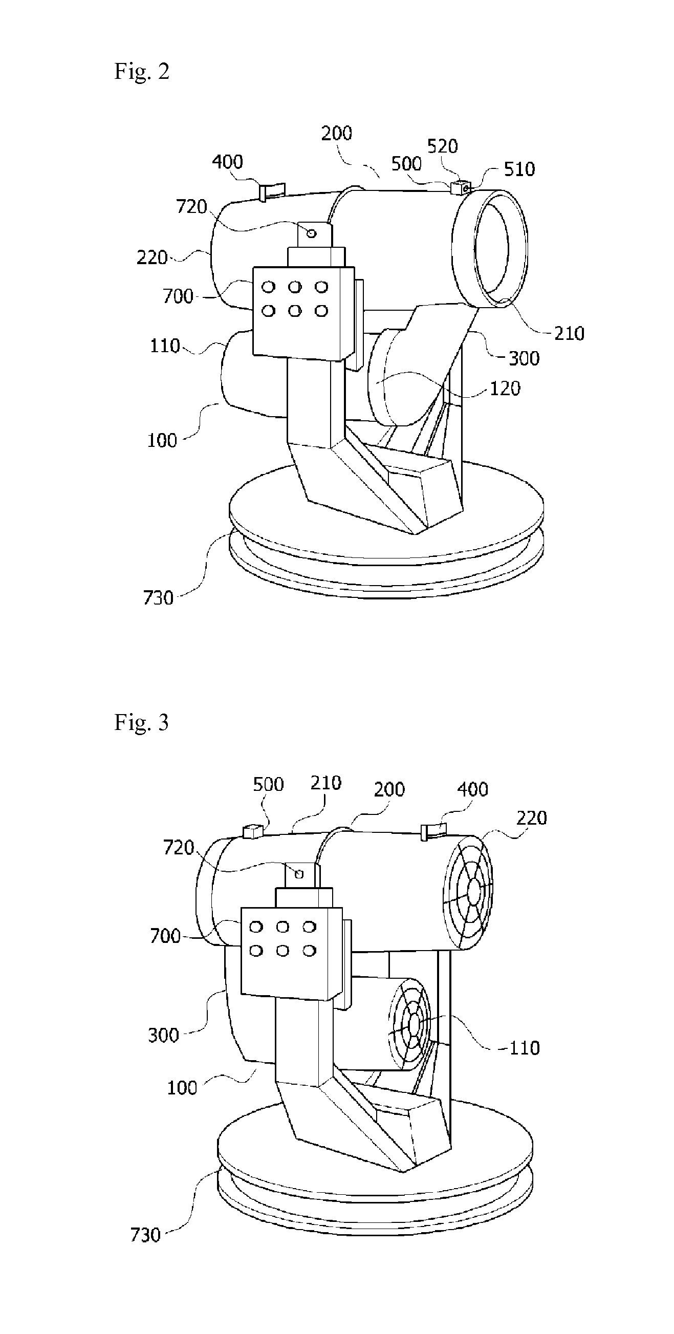
[0028]FIG. 1 is a block diagram illustrating a structure of a fog removal system according to the present invention. FIG. 2 is a front perspective view illustrating the fog removal system according to the presen...


PUM


Abstract

Disclosed is a fog removal system which can blow dry air onto roads, airport runways, harbors, or into coastal areas in which fog regularly occurs to reduce the relative humidity of atmospheric air down from about 100%, to thereby remove the fog. Particularly, in the fog removal system, a heating unit and a blowing unit may be connected to areas such as roads, airport runways, harbors, or coastal areas in which fog regularly occurs, to blow dry air generated in the heating unit over a long range using a strong blowing pressure from the blowing unit.

Description

CROSS REFERENCE TO PRIOR APPLICATIONS[0001]This application is a National Stage Application of PCT International Patent Application No. PCT / KR2012 / 000677 filed on Jan. 30, 2012, under 35 U.S.C. §371, which claims priority to Korean Patent Application No. 10-2011-0009338 filed on Jan. 31, 2011, which are all hereby incorporated by reference in their entirety.TECHNICAL FIELD[0002]The present invention relates to removal of fog by blowing dry air onto areas such as roads, airport runways, harbors, or coastal areas in which fog regularly occurs, to reduce a relative humidity of atmospheric air that has a relative humidity of 100%. More particularly, the present invention relates to a fog removal system in which a heating unit and a blowing unit are connected to areas such as roads, airport runways, harbors, or coastal areas in which fog regularly occurs, to transfer dry air generated by the heating unit to the blowing unit and blow the transferred dry air over a long range by using a st...

Claims


Application Information

Patent Timeline
Patent Type & Authority Patents(United States)
IPC IPC(8): A01G15/00E01H13/00A01G27/00B05B1/24
CPCE01H13/00
Inventor CHOI, JUN SEONGSONG, JONG SEOBCHOI, JUN CHEOLKANG, SUNG MIN
Owner KOREA MAINTENANCE & CONTROL
Learn More