
System for detecting an impact on an aircraft engine impeller wheel

a technology for aircraft engines and impeller wheels, applied in the field of automatic detection of impact on aircraft engine impeller wheels, can solve problems such as end damage to engines, progressive damage to turbines, and potential exposure of aircraft engines

Active Publication Date: 2015-01-27
SN DETUDE & DE CONSTR DE MOTEURS DAVIATION S N E C M A
View PDF18 Cites 3 Cited by
  • Summary
  • Abstract
  • Description
  • Claims
  • Application Information

AI Technical Summary

Benefits of technology

The present invention is a system that can detect impacts on an impeller wheel caused by objects ingested by an engine, in real-time and with minimal calculation time. Using pseudo-wavelets, the system can accurately represent the shocks absorbed on a blade and extract useful information on the impact. The system can also automatically recognize any impact information and confirm if it describes a shock or a simple electronic perturbation. The recording or emission of a maintenance notification can help to quickly repair any damage and prevent long-term degradation of engine performance. Thus, the system allows for global monitoring of the fan's health and ensures timely maintenance.

Problems solved by technology

In the course of their missions, aircraft engines are potentially exposed to the ingestion of different objects which can damage them.
On the other hand, below around 30 grammes, the impact is no longer felt by the pilot and the damage caused by this type of ingestion may evolve slowly and bring about in the end damage to the engine.
An example of this type of ingestion is the impact of a sparrow on the impeller wheel of the HP turbine, the remains of which can obstruct the ventilation holes (HP nozzles) leading to the progressive damaging of the turbine.
This solution has nevertheless the drawback of requiring an additional instrumentation which is detrimental to the mass balance of the aircraft.
Furthermore, it does not enable the impacted blade to be identified.

Method used


Image

  • System for detecting an impact on an aircraft engine impeller wheel
  • System for detecting an impact on an aircraft engine impeller wheel
  • System for detecting an impact on an aircraft engine impeller wheel

Examples


Embodiment Construction

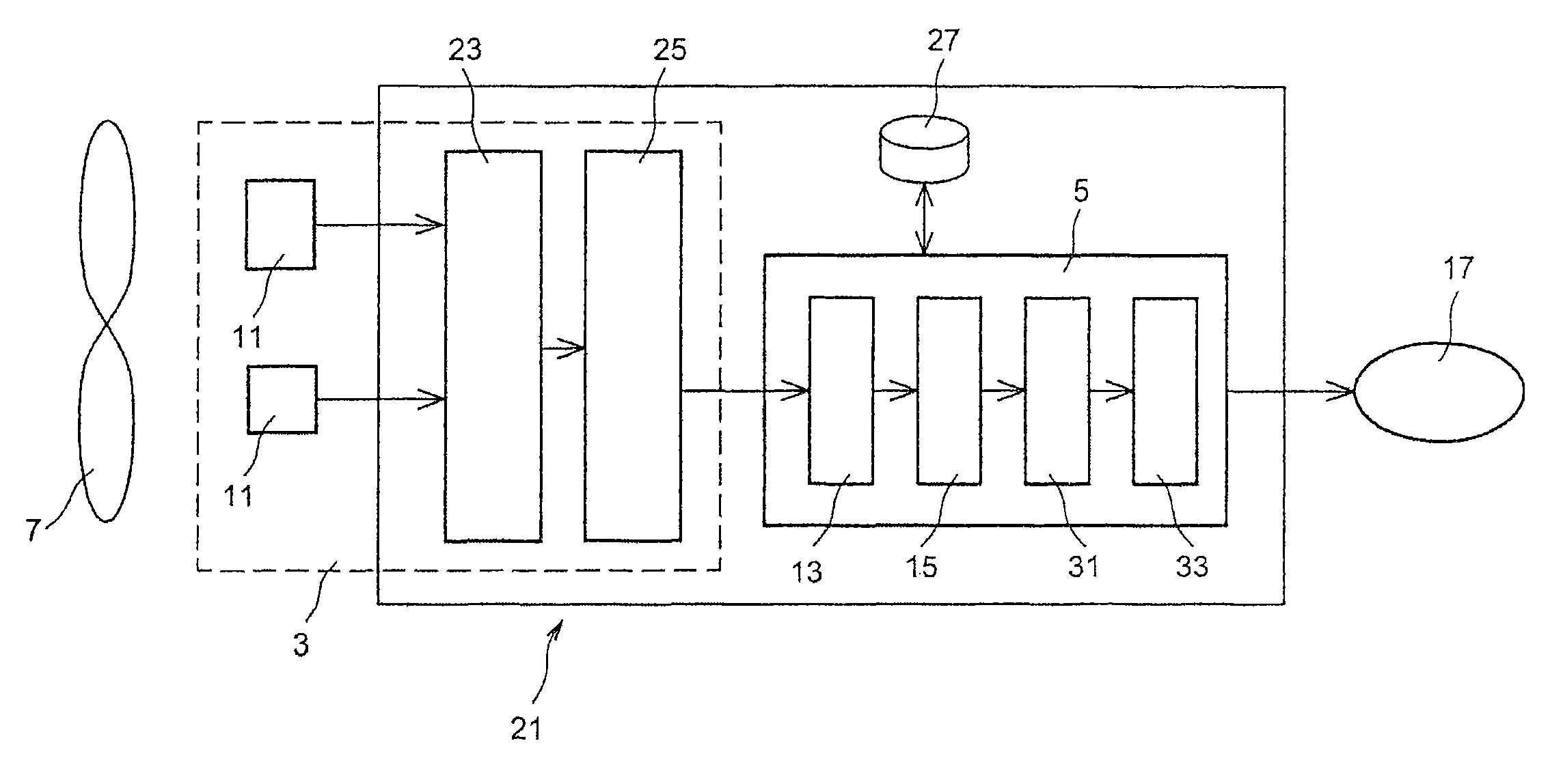
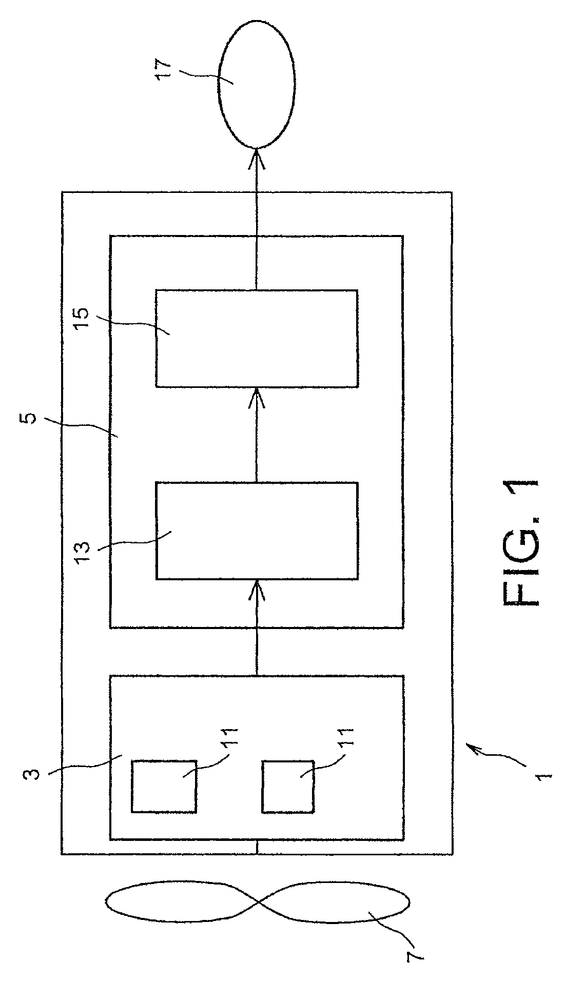
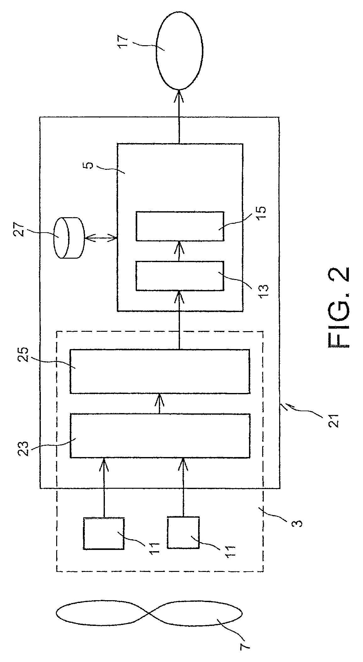
[0009]The present invention is defined by a system for detecting an impact on an impeller wheel of an aircraft engine, comprising:[0010]acquisition means for acquiring a revolutions per minute of said engine and a series of deflection signals representative of the deflections on the blades of said impeller wheel at said revolutions per minute, and[0011]correlation means to construct signals for detecting impact on said impeller wheel by correlating each of the deflection signals with a predetermined signature of a shock on a blade at said revolutions per minute.

[0012]The system of the present invention makes it possible to detect in real time, in a reliable manner, and with a minimal calculation time, any impact on the impeller wheel caused by an object of any weight ingested by the engine. More particularly, said system makes it possible to detect with precision any impact not felt by the pilot caused for example by a light foreign body.

[0013]Thus, the detection system according to...


PUM


Abstract

A method and a system for detecting an impact on an impeller wheel of an aircraft engine. A device acquires a revolutions per minute of the engine and a series of deflection signals representative of the deflections on the blades of the impeller wheel at the revolutions per minute. A device constructs signals for detecting impact on the impeller wheel by correlating each of the deflection signals with a predetermined signature of a shock on a blade at the revolutions per minute.

Description

TECHNICAL FIELD[0001]The present invention relates to the field of engine surveillance systems and, more particularly, the automatic detection of an impact on an impeller wheel of an aircraft engine.PRIOR ART[0002]In the course of their missions, aircraft engines are potentially exposed to the ingestion of different objects which can damage them. These objects are in general FOD (Foreign Object Damage) but may optionally be small parts (for example rivets or bolts) detached from the engine, DOD (Domestic Object Damage).[0003]The ingestion of an object constitutes the main cause of flight D&C (Delays and Cancelation). In fact, in most cases, the impact is not noticed by the pilot during the flight and the finding on the blade is made during the control of the airplane just before taking off again.[0004]Studies have shown that for a FOD having a weight greater than around 30 grammes, the probability that the impact is felt by the pilot becomes significant. On the other hand, below aro...

Claims


Application Information

Patent Timeline
Patent Type & Authority Patents(United States)
IPC IPC(8): G06F7/00B64D45/00F01D21/00F01D21/04F02C7/04
CPCB64D45/00F01D21/003F01D21/04F02C7/04F05D2260/80Y02T50/671Y02T50/60G01H1/006
Inventor TOURIN, DAVIDGEREZ, VALERIONICQ, GEOFFROY
Owner SN DETUDE & DE CONSTR DE MOTEURS DAVIATION S N E C M A
Learn More