Swimming pool brush

a technology for cleaning devices and swimming pools, which is applied in the direction of gymnasiums, buildings, construction, etc., can solve the problems of not being able unable to adequately clean all corners, and limiting the direction of bristles oriented generally downward, etc., to achieve clean all other surface areas, simple, efficient, and easy to clean

Active Publication Date: 2015-02-03
ASIA CONNECTION
View PDF16 Cites 3 Cited by
  • Summary
  • Abstract
  • Description
  • Claims
  • Application Information

AI Technical Summary

Benefits of technology

[0012]The present invention advantageously provides a simple, efficient pool brush for easily cleaning all corners where walls and floors come together, areas where different planar walls intersect, edge areas where walls meet floors, around stairs, seats and the like, while simultaneously being able to clean all other surface areas of a pool. Furthermore, the pool brush herein can clean the underside of pool steps without turning the brush over, which is a significant advantage.

Problems solved by technology

However, these references are limited to having bristles oriented generally downward, and are not capable of adequately cleaning all corners where walls and floors come together, areas where different planar walls intersect, edge areas where walls meet floors, and around stairs, seats and the like.
U.S. Pat. No. Des. 257,521 to Piero; and U.S. Pat. No. 4,176,419 to MacDonald each describe other pool brushes where the bristles are only oriented about part of the perimeter edges of the brush head, and are also not capable of adequately cleaning all corners where walls and floors come together, areas where different planar walls intersect, edge areas where walls meet floors, around stairs, seats and the like.
U.S. Pat. No. 2,083,134 to Wood shows a complex brush for “cleaning vats” having separately positioned bristle heads attached to two parallel brush heads, and also would not appear to be capable of adequately cleaning all corners where walls and floors come together, areas where different planar walls intersect, edge areas where walls meet floors, around stairs, seats and the like.
However, Gilman requires a handle parallel to a small rectangular pad brush head with only rounded bristles on one side edge and does not describe any application for cleaning pools and can not be used for adequately cleaning all corners where walls and floors come together, areas where different planar walls intersect, edge areas where walls meet floors, around stairs, seats and the like.

Method used


Image

  • Swimming pool brush
  • Swimming pool brush
  • Swimming pool brush

Examples


Embodiment Construction

)

[0017]It will be understood that any numerical range recited herein is intended to include all sub-ranges within that range.

[0018]It will be further understood that any compound, material or substance which is expressly or implicitly disclosed in the specification and / or recited in a claim as belonging to a group of structurally, compositionally and / or functionally related compounds, materials or substances includes individual representatives of the group and all combinations thereof.

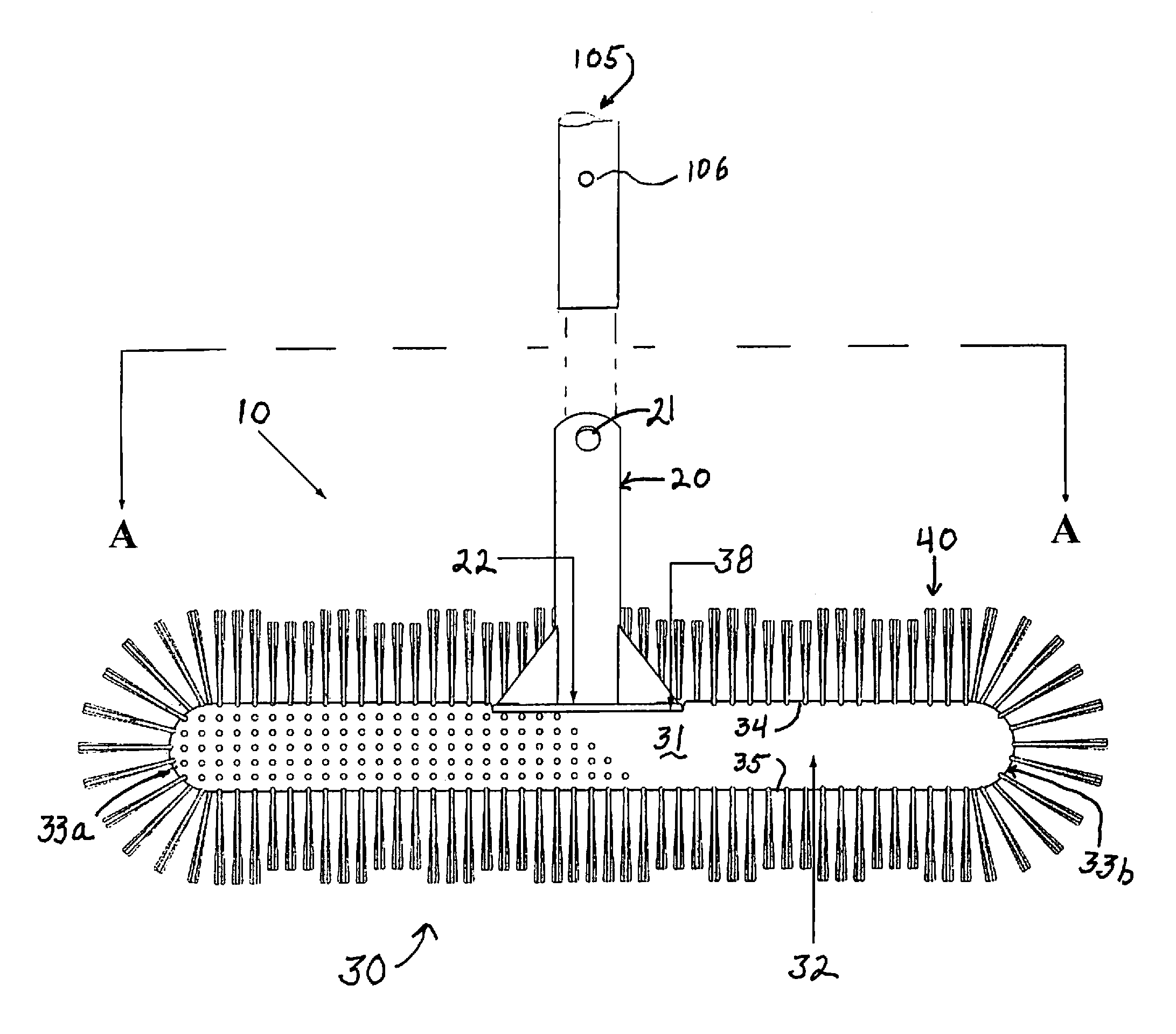
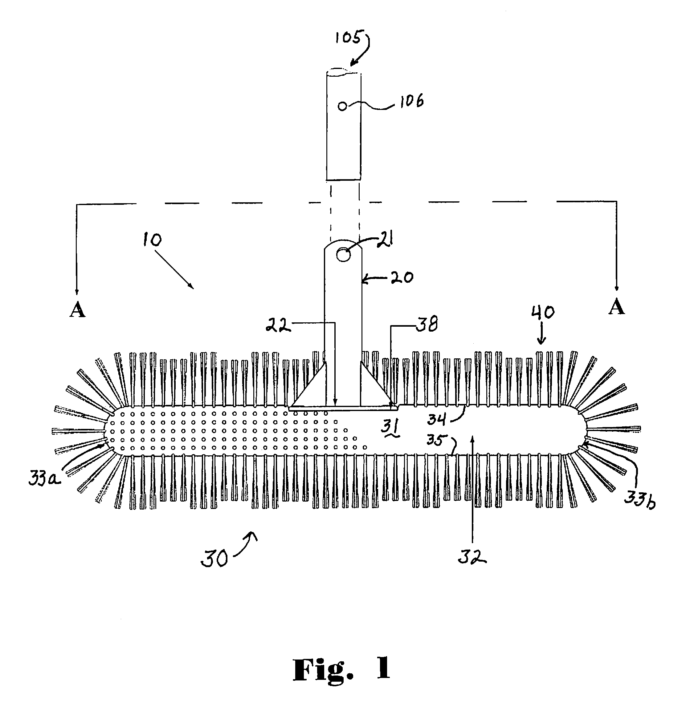
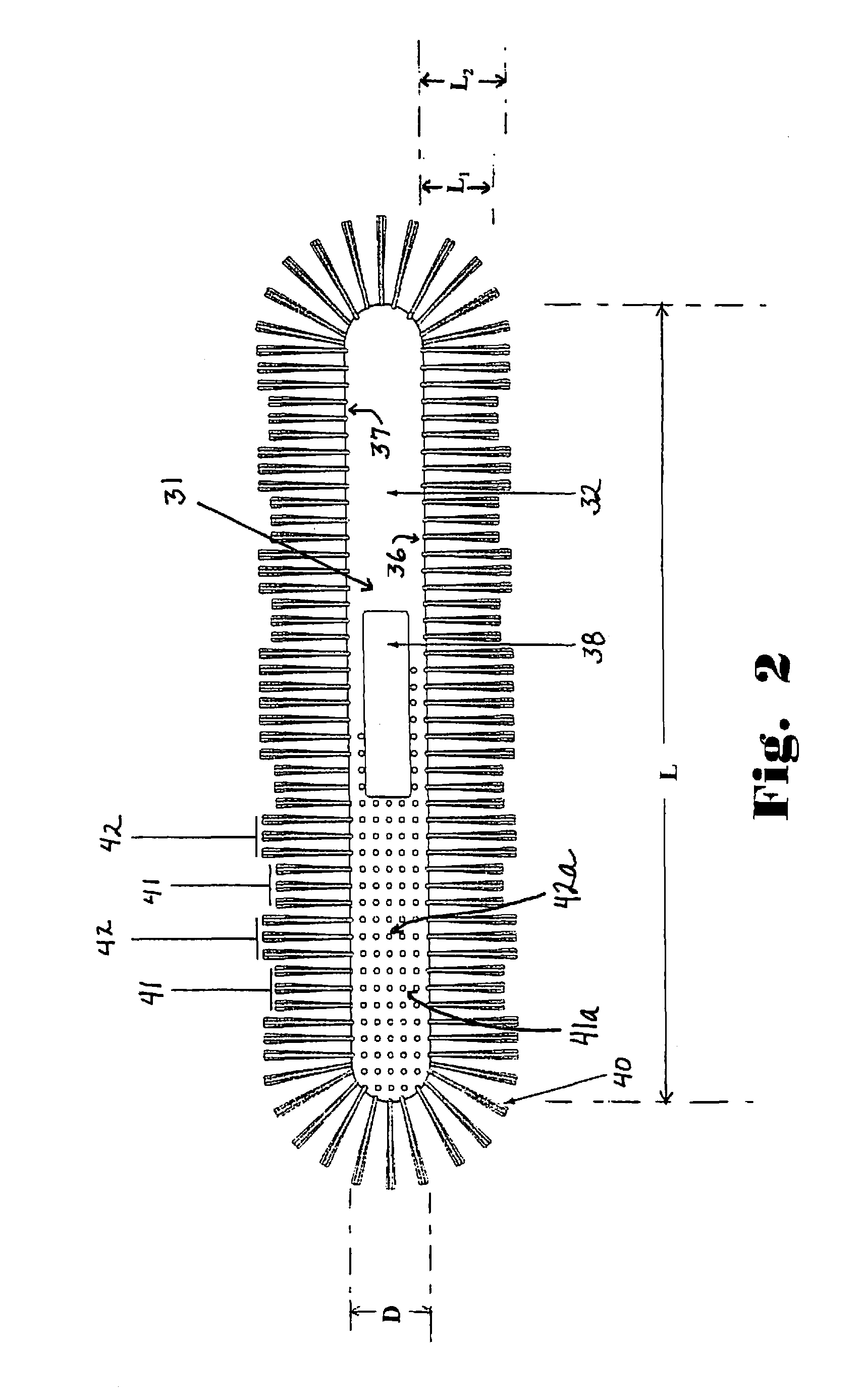
[0019]A preferred embodiment of the pool brush includes a handle receiver configured to receive an elongated handle, and a brush head having a cylindrical body with rounded front, bottom and rear sides. The cylindrical body having opposite semi-spherical rounded ends and a mid-portion is perpendicularly connected to the elongated handle, where the handle is longer than the brush head.

[0020]The bristles are perpendicularly mounted to the front, bottom and rear rounded surface sides, as well as to the se...


PUM


Abstract

A pool brush includes a handle receiver; and a brush head attached to the handle receiver, the brush head having a body and a plurality of bristles extending from said body. The body includes a cylindrical portion having rounded top, bottom, front and rear sides, and opposite end portions, and the plurality of bristles includes bristles radially extending 360 degrees around the cylindrical portion of the body and from the end portions. The plurality of bristles includes a plurality of bundles of relatively longer bristles and a plurality of bundles of relatively shorter bristles, wherein the bundles of relatively longer bristles are in arrays in an alternating arrangement with arrays of the bundles of shorter bristles.

Description

CROSS REFERENCE TO RELATED APPLICATIONS[0001]The present application claims priority to U.S. Provisional application No. 61 / 639,253 filed Apr. 27, 2012, which is herein incorporated by reference.BACKGROUND[0002]1. Field of the Invention[0003]This invention relates to swimming pool cleaning devices, and in particular to a cylindrical swimming pool brush head having rounded ends with bristles perpendicularly mounted along the rounded sides so that hard to reach narrow angled areas such as corners, stairs, and seat areas can be cleaned.[0004]2. Background of the Art[0005]Swimming pool brushes have been around for many years. Most traditional brushes have an elongated handle connected to a brush head. See for example U.S. Pat. No. D. 351,948 to Getchell; U.S. Pat. No. 3,296,643 to Fortune; U.S. Pat. No. 4,637,087 to Feinberg; U.S. Pat. No. 4,703,535 to Nehls; U.S. Pat. No. 4,733,427 to Conrad; U.S. Pat. No. 4,783,868 to O'Callaghan; and U.S. Pat. No. 5,487,397 to Bean. However, these re...

Claims


Application Information

Patent Timeline
Patent Type & Authority Patents(United States)
IPC IPC(8): E04H4/16A46B5/00A46B9/02
CPCA46B9/02A46B5/0095A46B9/026E04H4/1609
Inventor SACCOCCIO, MITCHBONELLI, JONATHAN
Owner ASIA CONNECTION
Why Eureka
Try Eureka