Hot melt glue applicator

a technology of applicator and hot melt glue, which is applied in the direction of superimposed coating process, liquid/solution decomposition chemical coating, coating, etc., can solve the problems of relatively slow cooling, limited production to approximately 4-5 parts per minute, etc., and achieves the effect of reducing the use of glue, reducing scrap, and speeding up drying

Active Publication Date: 2015-02-03
MANNHUMMEL PUROLATOR FILTERS
View PDF8 Cites 1 Cited by
  • Summary
  • Abstract
  • Description
  • Claims
  • Application Information

AI Technical Summary

Benefits of technology

[0006]It is one object of this invention to improve filter element output. This object, and others, may be achieved by way of an apparatus for transferring adhesive material to portions of filter elements that are displaced relative to the apparatus including a dispenser from which heated adhesive material is discharged, a transfer arrangement that receives discharged adhesive material and transfers the discharged adhesive material to the adhesive material receiving portions of the elements that are displaced relative to the apparatus, and a cooling arrangement. The cooling arrangement cooperates with the transfer arrangement to cool the discharged adhesive material while the adhesive material is carried by the transfer arrangement to the adhesive material receiving portions of the elements.
[0010]In one preferred configuration of this invention, the glue applicator has two wheels that accumulate adhesive from glue guns and reapply even beads to the filter elements without having the elements adhere to the application wheel. This applicator permits a reduction in glue usage by 50%, minimizes scrap preventing the glue from sticking to the filter bag with faster drying, and enhances the ability to apply adhesive at significantly increased rates. Since each wheel is cold, hot melt glue hardens against the wheel, leaving the face side soft and tacky, facilitating transfer to a passing filter element.
[0011]The unique design described and illustrated is intended to allow the glue to become more rigid on its surface side but remain soft enough to be applied to the element, resulting in a smooth flat surface on the finished product. One result of this design is an increase in the number of parts processed per minute, preventing the “off-stack” of filters needing to be rescheduled for processing.

Problems solved by technology

Cooling, however, is relatively slow; with a conveyor linear speed of about 15.5 feet per minute, production is limited to approximately 4-5 parts per minute.

Method used


Image

  • Hot melt glue applicator
  • Hot melt glue applicator
  • Hot melt glue applicator

Examples


Embodiment Construction

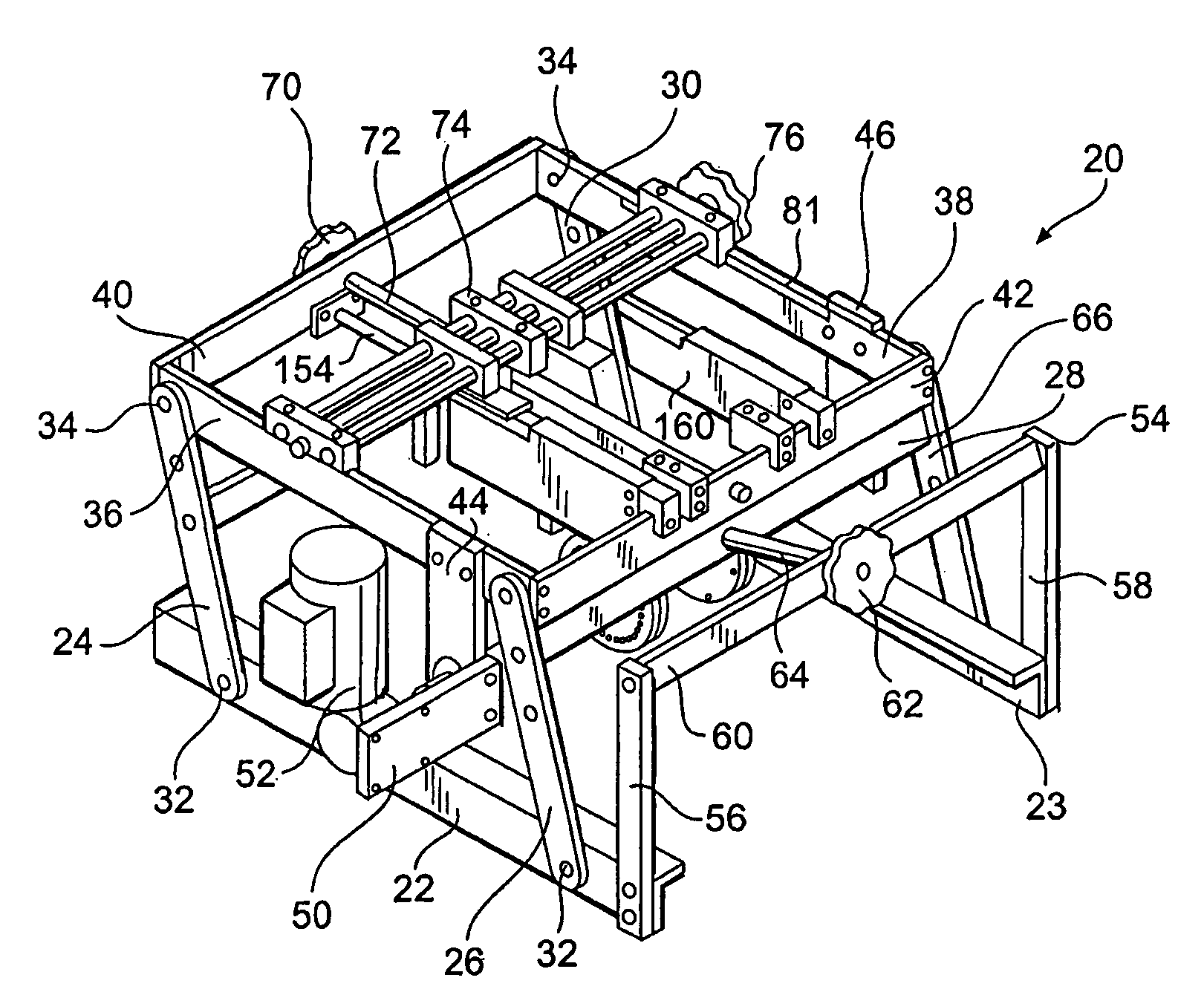
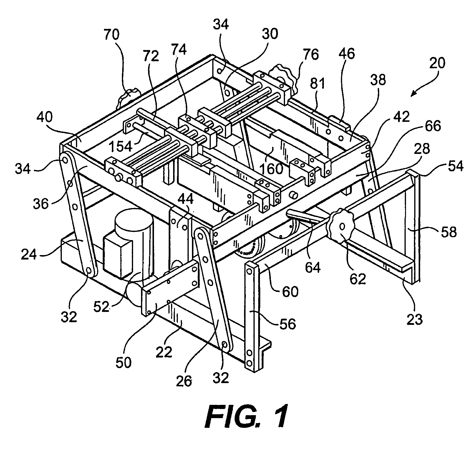
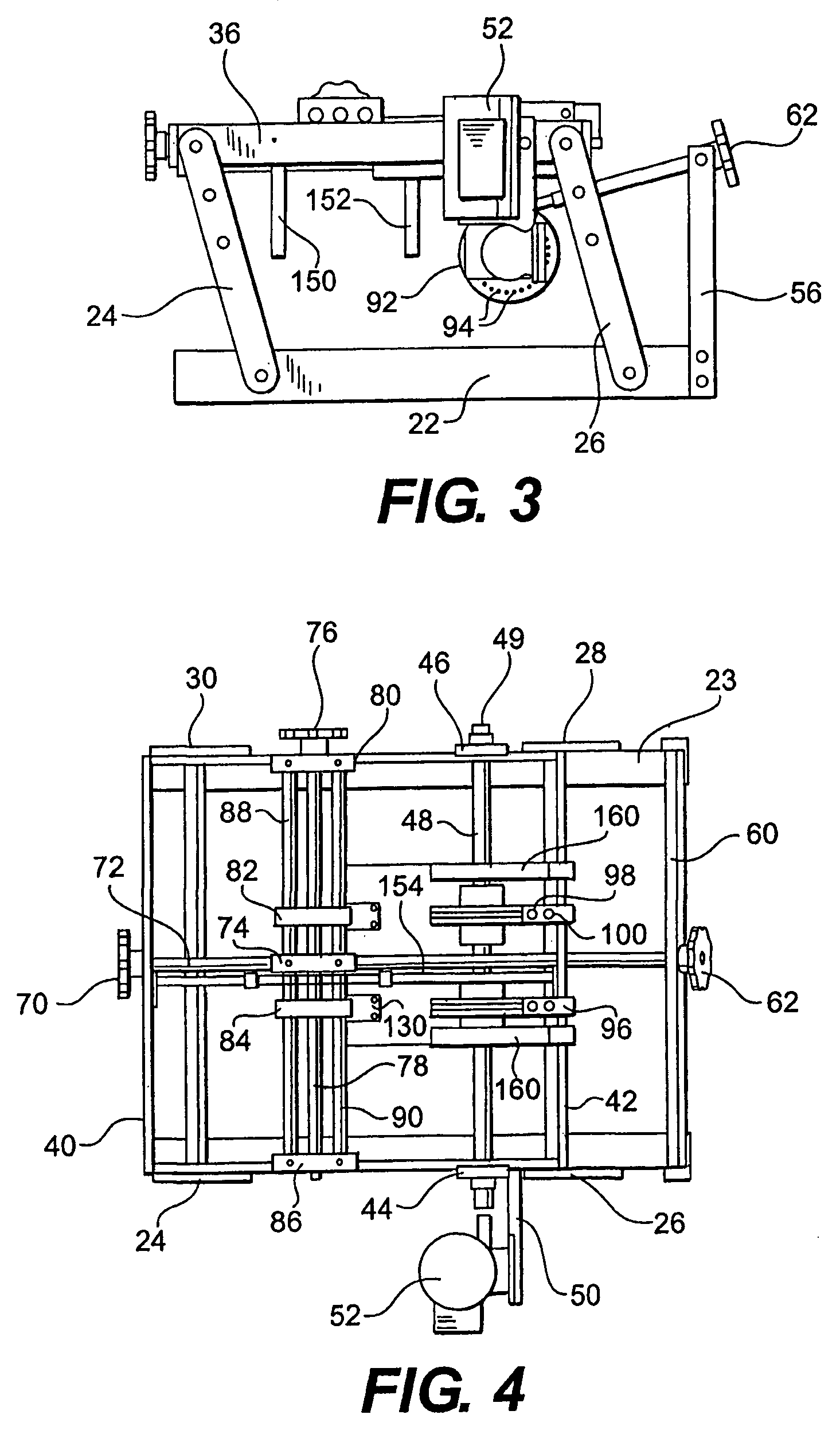
[0017]FIGS. 1-4 show a first configuration of a frame 20 for the glue applicator assembly, with the glue bead applicator nozzle and certain other elements removed for clarity. The glue applicator frame 20 includes a pair of base elements 22, 23, which, as illustrated in the figures, are formed by angled beams having approximately “L” shaped cross sections. These base elements are configured and dimensioned to fit on and be secured to stationary side rails of a filter transport device having a conveyor belt as will be described. Bolts, screws, or other appropriate connections 32 pivotally attach first ends of left side legs 24, 26 to the left side base element 22. First ends of right side legs 28, 30 are similarly attached to the right side base element 23. In the same way, second ends of the left side legs 24, 26 are pivotally attached by connections 34 to ends of a left side rail 36, while second ends of the right side legs 28, 30 are pivotally attached by connections 34 to a right...


PUM

PropertyMeasurementUnit
diameteraaaaaaaaaa
adhesiveaaaaaaaaaa
thicknessesaaaaaaaaaa

Abstract

An apparatus for transferring adhesive material to portions of filter elements that are displaced relative to the apparatus includes a dispenser from which heated adhesive material is discharged, a transfer arrangement that receives discharged adhesive material and transfers the discharged adhesive material to the portions of the elements as they are displaced, and a cooling arrangement. The cooling arrangement cooperates with the transfer arrangement to cool the discharged adhesive material while the adhesive material is carried by the transfer arrangement to the adhesive material receiving portions of the elements. A process by which adhesive material is transferred to adhesive material receiving portions of the filter elements, as well as an air line panel filter produced by that process, are also discussed.

Description

BACKGROUND OF THE INVENTION[0001]1. Field of the Invention[0002]This invention concerns an apparatus used during manufacture of air line panel filters or for any customer required panel filter glue applications, as well as to a process of manufacturing such filters.[0003]2. Description of Related Art[0004]One known apparatus for application of glue to filter elements is available from Graphischer Maschinenbau Nordhausen GmbH (“GMN”). During operation of this apparatus, glue is applied to a slick fiberglass belt moving at the same speed as a conveyor. As a filter element comes in contact with the belt, glue is transferred to the top of that element, with glue passing from the GMN glue gun at 400° F. The filter element is held between the belt and the conveyor for 28 inches while the glue cools. As the filter element exits the apparatus, the glue peels away and stays on top of the filter element.[0005]Glue of the sort typically used in filter fabrication separates from the belt at app...

Claims


Application Information

Patent Timeline
Patent Type & Authority Patents(United States)
IPC IPC(8): B05C1/06B05C5/00B05C1/00B05C1/02B05C1/08B05C11/10B05D1/28B05D5/10
CPCB05C1/0808B05C1/003B05C1/0813B05C11/1021B05D1/28B05C1/02B05D5/10
Inventor WHITEHURST, JAMES STEVEN
Owner MANNHUMMEL PUROLATOR FILTERS
Why Eureka
Try Eureka