Homogenizing mixer with an agitating unit having a lifter unit

a technology of lifting unit and agitating unit, which is applied in the direction of mixing, rotary stirring mixer, transportation and packaging, etc., can solve the problems of complicated configuration facilities, overloaded, and inability to operate the agitator and the driving unit, so as to reduce failure factors, simplify the agitating unit, and save costs

Inactive Publication Date: 2015-02-03
LEE KI NAM
View PDF10 Cites 4 Cited by
  • Summary
  • Abstract
  • Description
  • Claims
  • Application Information

AI Technical Summary

Benefits of technology

[0012]To solve the above problems of the conventional art, it is an object of the present invention to provide a homogenizing mixer whose structure is improved so as to rotate and lift an agitator during agitating materials that are put in a container, and have a simply lifting structure and a structure of conveniently discharging homogenized materials.
[0018]A homogenizing mixer according to the present invention uses an agitating unit that can be lifted at the lower portion of a container, to thus homogenize a plurality of materials whose properties differ from each other. Accordingly, the agitating unit becomes simplified, to thus save cost, reduce failure factors, and conveniently discharge homogenized materials in conjunction with a descending operation of the agitating unit, without having a separate discharging unit. As a result, the homogenizing mixer according to the present invention does not only have a simple structure but also functions conveniently.

Problems solved by technology

Since the conventional homogenizing mixer is configured so that the agitator and the driving unit are activated at the upper side of the container, there are problems that configurational facilities necessary to operate the agitator and the driving unit are complicated and overloaded.

Method used


Image

  • Homogenizing mixer with an agitating unit having a lifter unit
  • Homogenizing mixer with an agitating unit having a lifter unit
  • Homogenizing mixer with an agitating unit having a lifter unit

Examples


Embodiment Construction

[0026]A homogenizing mixer according to a preferred embodiment of the present invention will be described with reference to the accompanying drawings, FIGS. 1 to 6.

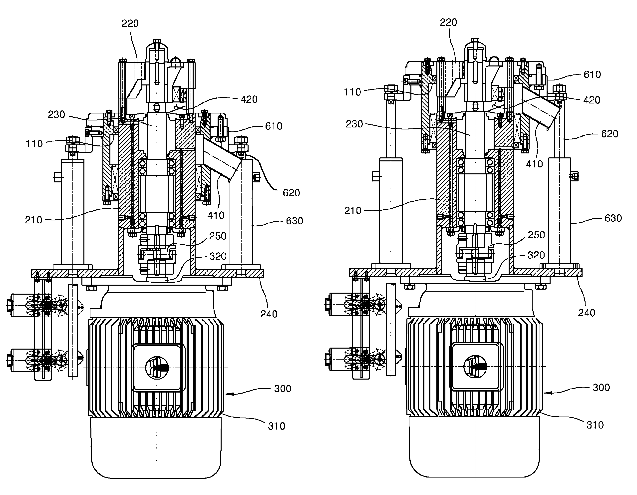
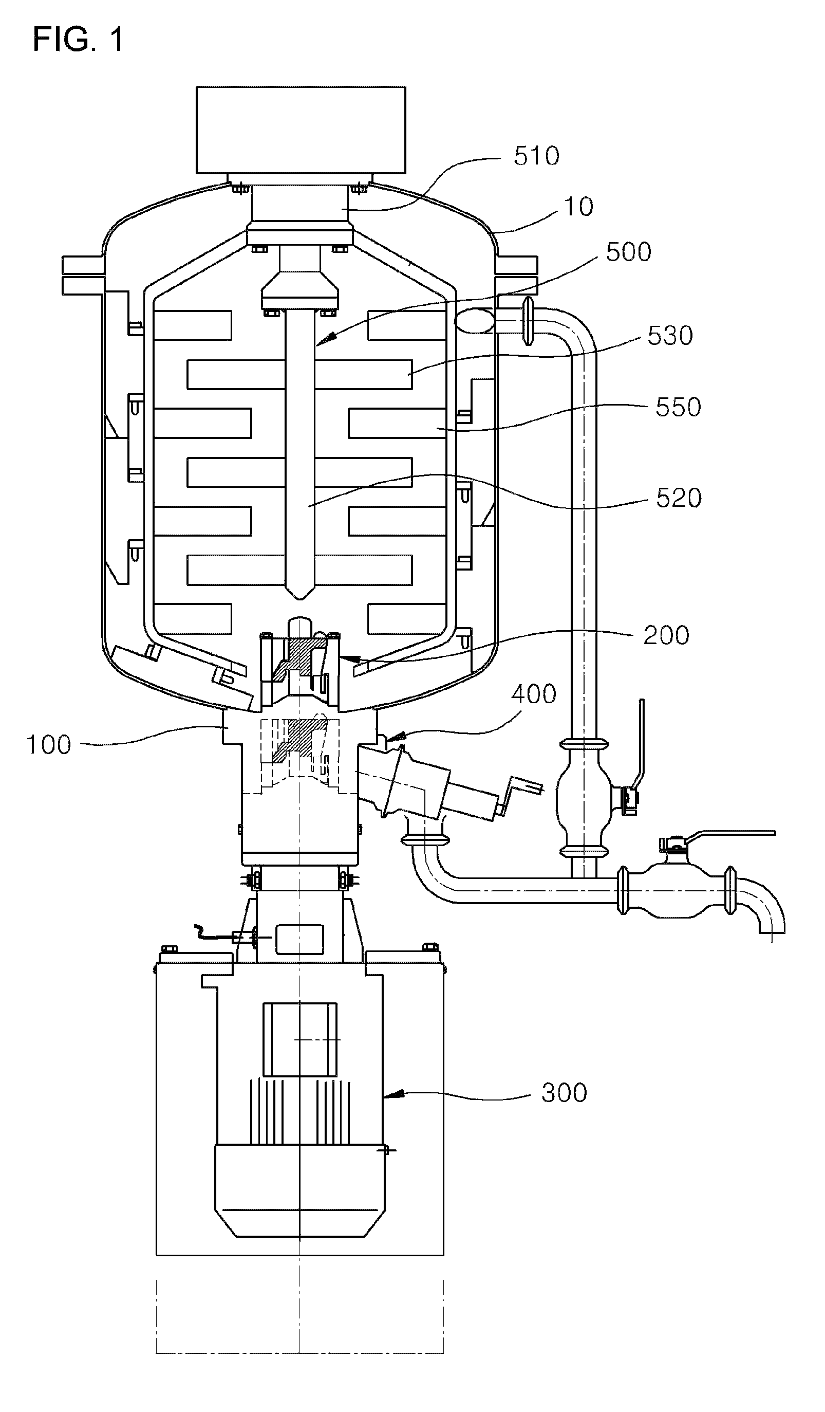
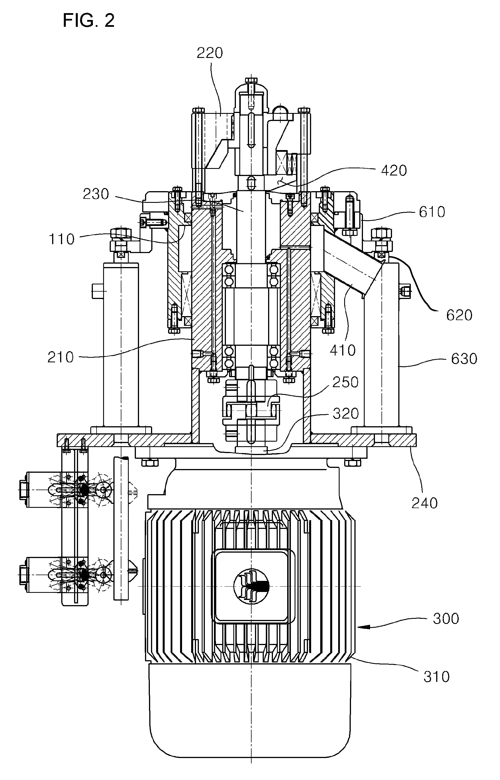
[0027]Referring to FIGS. 1 to 6, a homogenizing mixer according to a preferred embodiment of the present invention, includes: a container 10 having an internal space so that materials whose properties differ are contained therein; a fixed frame 100 that is disposed so as to be fixed at the bottom of the container 10, and communicates from the inside of the container 10; an agitating unit 200 that is disposed in the fixed frame 100, so as to be lifted up and down by medium of an lifting unit, and that agitates the materials contained in the container 10; a driving unit 300 that is disposed on the bottom of the agitating unit 200 for transferring a rotational driving force for the agitating unit 200; and a discharging unit 400 that is stirred by the agitating unit 200 and discharging a homogenized material to the outside of...


PUM


Abstract

Provided is a homogenizing mixer including: a container having an internal space so that materials whose properties differ are contained therein; a fixed frame that is disposed so as to be fixed at the bottom of the container, and communicates from the inside of the container; an agitating unit that is disposed in the fixed frame, so as to be lifted up and down by medium of an lifting unit, and that agitates the materials contained in the container; a driving unit that is disposed on the bottom of the agitating unit for transferring a rotational driving force for the agitating unit; and a discharging unit that is coupled to the agitating unit and discharging a homogenized material to the outside of the mixer.

Description

BACKGROUND OF THE INVENTION[0001]1. Field of the Invention[0002]The present invention relates to a homogenizing mixer that mixes and homogenizes a liquid-phase material that is a raw material with another liquid-phase material or powder material whose property differs from that of the raw material.[0003]2. Description of the Related Art[0004]In general, homogenizing mixers are chiefly used for manufacturing cosmetics or paints, and play a role of mixing a raw material and a blend material both properties of which differ from each other with a viscous material, to thereby perform a function of homogenizing the mixture.[0005]Here, both the raw material and the blend material may be liquid-phase materials, or a mixture or a liquid-phase material and a minute powder material.[0006]A conventional homogenizing mixer includes a substantially hemispherical tubular container, an agitator, a driving unit that driving units the agitator, and a main body frame.[0007]The container is a vessel th...

Claims


Application Information

Patent Timeline
Patent Type & Authority Patents(United States)
IPC IPC(8): B01F7/16B01F5/10B01F7/00B01F7/18
CPCB01F7/166B01F5/104B01F7/00116B01F7/00141B01F7/00633B01F7/162B01F7/1635B01F7/183B01F25/52B01F27/0721B01F27/0724B01F27/191B01F27/808B01F27/8111B01F27/84B01F27/902
Inventor KIM, CHUNG HWANCHO, DEOK GY
Owner LEE KI NAM
Why Eureka
Try Eureka