Assembly of a part that is brittle

a technology of brittle parts and parts, applied in the field of parts assembly, can solve the problems of silicon parts breaking, affecting the stability of the part, and requiring extremely delicate application

Active Publication Date: 2015-02-03
ETA SA MFG HORLOGERE SUISSE
View PDF13 Cites 13 Cited by
  • Summary
  • Abstract
  • Description
  • Claims
  • Application Information

AI Technical Summary

Benefits of technology

[0005]It is an object of the present invention to overcome all or part of the aforecited drawbacks by providing an adhesive-free assembly which can secure a part made of a material that is brittle, i.e. with no plastic domain, to a member comprising a ductile material, such as, for example, a metal or metal alloy.
[0007]This configuration advantageously enables the assembly comprising the part-intermediate part-member to be secured without bonding to an ordinary, precision controlled member, while ensuring that the part is not subject to destructive stresses, even if it is formed, for example, from silicon.

Problems solved by technology

However, bonding is not satisfactory as regards long term hold.
Moreover, the operation requires extremely delicate application which makes it expensive.
However, the shape variants proposed in this document are not satisfactory and either result in the silicon part breaking during assembly, or do not bind the parts sufficiently well to each other.

Method used


Image

  • Assembly of a part that is brittle
  • Assembly of a part that is brittle
  • Assembly of a part that is brittle

Examples


first embodiment

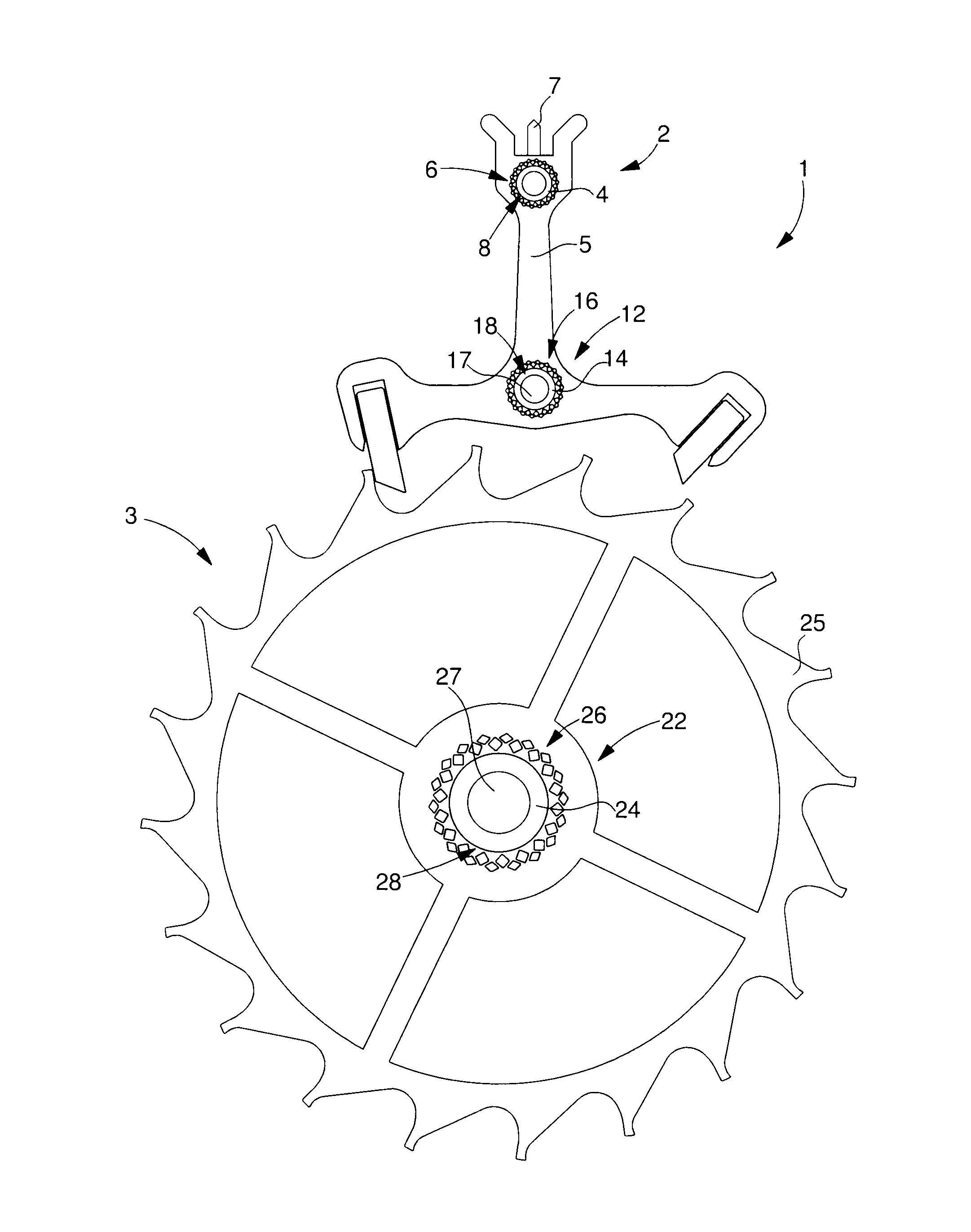
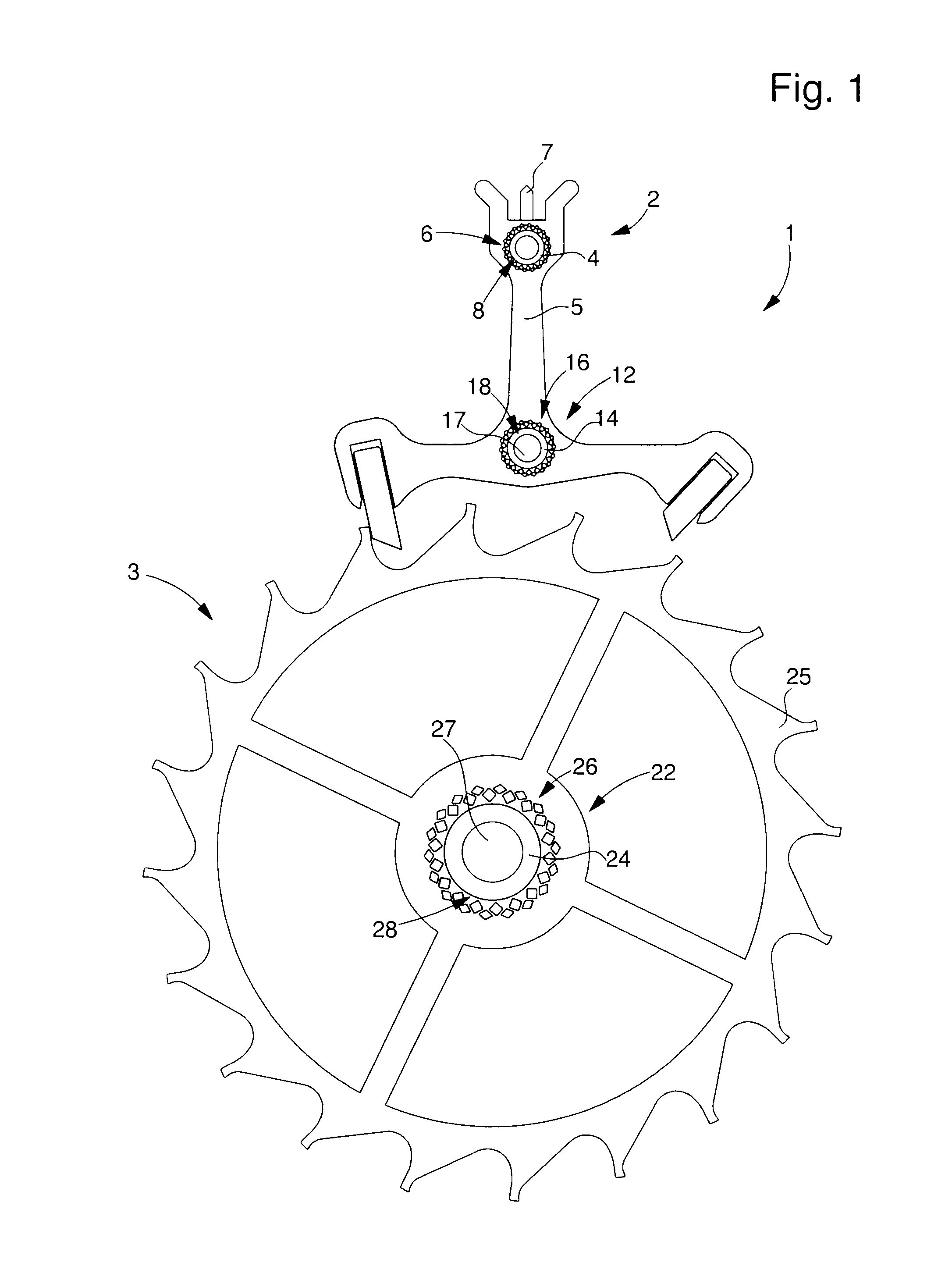
[0049]Examples of pierced holes are shown in FIGS. 3 to 8. illustrated in FIGS. 3 to 6, the pierced holes are formed at a distance from and around the circular aperture by two series of diamond-shaped holes distributed in a quincunx arrangement so as to form beams arranged in secant V-shapes.

[0050]FIG. 3 is a diagram of pierced holes 6, 16, 26 of FIGS. 1 and 2. For more simplicity, only the wheel 3 references are used again in FIG. 3. FIG. 3 shows pierced holes 26, which preferably pass through the entire thickness of body 25, made of fragile material. Pierced holes 26 are distributed at a distance from and around circular aperture 28 which is also preferably formed to pass through the entire thickness of body 25 made of fragile material.

[0051]As seen in FIG. 3, pierced holes 26 form a first series of holes 31, the farthest from aperture 28, and a second series of holes 33, which are diamond-shaped and in a quincunx arrangement. FIG. 3 shows that pierced holes 31, 33 thus form V-sh...

second embodiment

[0058] illustrated in FIGS. 7 and 8, the pierced holes are formed at a distance from and around the circular aperture by a first series of oblong holes distributed in a quincunx arrangement with a second series of triangular holes, the second series being closest to the circular aperture, each triangular hole communicating with the circular aperture via a notch so as to form beams that are radially moveable according to the thickness of the oblong holes.

[0059]Thus, FIG. 7 shows pierced holes 46 which preferably pass through the entire thickness of body 25, made of fragile material. Pierced holes 46 are distributed at a distance from and around circular aperture 28 which is also preferably formed to pass through the entire thickness of body 25 made of fragile material.

[0060]As seen in FIG. 7, pierced holes 46 form a first series of oblong holes 51 and a second series of triangular holes 53. According to the second embodiment, the two series of holes 51, 53 are arranged in a quincunx ...


PUM

PropertyMeasurementUnit
widthaaaaaaaaaa
widthaaaaaaaaaa
diameteraaaaaaaaaa

Abstract

An assembly including a member made of a first material, which is axially driven into a circular aperture of a part made of a second material that is brittle, using an intermediate part made of a third material and mounted between the member and the part is disclosed. The intermediate part is a continuous cylinder including a hole for receiving the member so that the intermediate part absorbs radially and in a uniform manner, at least part of the axial driving force of the member. The part includes pierced holes forming elastic deformation units distributed around the circular aperture thereof for absorbing any of the radial force not absorbed by the intermediate part, so as to secure the assembly in a non-destructive manner for the part.

Description

[0001]This application claims priority from European Patent Application No. 10187740.5 filed Oct. 15, 2010, the entire disclosure of which is incorporated herein by reference.FIELD OF THE INVENTION[0002]The invention relates to the assembly of a part, made of a material that is brittle, i.e. having no plastic domain, to a member comprising a different type of material.BACKGROUND OF THE INVENTION[0003]Current assemblies including a silicon-based part are generally secured by bonding. However, bonding is not satisfactory as regards long term hold. Moreover, the operation requires extremely delicate application which makes it expensive.[0004]EP Patent No. 1 850 193 discloses a first, silicon-based part which is assembled on a metal arbour using an intermediate metallic part. However, the shape variants proposed in this document are not satisfactory and either result in the silicon part breaking during assembly, or do not bind the parts sufficiently well to each other.SUMMARY OF THE INV...

Claims


Application Information

Patent Timeline
Patent Type & Authority Patents(United States)
IPC IPC(8): G04B13/02G04B15/14G04B17/32
CPCG04B13/025G04B13/022G04B15/14G04B17/32Y10T29/49579
Inventor CONUS, THIERRYVERARDO, MARCOKOHLER, FREDERICSAGLINI, IGORCABEZAS JURIN, ANDRESJACOT, JACQUESPERRET-GENTIL, MAXENCE
Owner ETA SA MFG HORLOGERE SUISSE
Why Eureka
Try Eureka