Electrical signal connector

a technology of electrical signals and connectors, applied in the direction of coupling devices, two-part coupling devices, electrical equipment, etc., can solve the problems of high installation time and labor, and achieve the effect of preventing angular deviation of coaxial cables and saving installation time and labor

Inactive Publication Date: 2015-02-03
LEE CHUNG YU
View PDF5 Cites 26 Cited by
  • Summary
  • Abstract
  • Description
  • Claims
  • Application Information

AI Technical Summary

Benefits of technology

[0008]The present invention has been accomplished under the circumstances in view. It is therefore the main object of the present invention to provide an electrical signal connector for connecting a coaxial cable to a mating connector, which facilitates quick installation without any hand tool, saving much installation time and labor, preventing angular deviation of the coaxial cable, and increasing yields.
[0010]Further, after the locknut, the metal central tube, the chuck unit and the actuation sleeve are assembled, the user can insert the coaxial cable into the electrical signal connector, and then manually move the actuation sleeve relative to the chuck unit to compress the longitudinal clamping strips of the collar, and thus the coaxial cable is quickly and firmly secured to the electrical signal connector, saving much installation time and labor and preventing angular deviation of the coaxial cable.

Problems solved by technology

Further, after the locknut, the metal central tube, the chuck unit and the actuation sleeve are assembled, the user can insert the coaxial cable into the electrical signal connector, and then manually move the actuation sleeve relative to the chuck unit to compress the longitudinal clamping strips of the collar, and thus the coaxial cable is quickly and firmly secured to the electrical signal connector, saving much installation time and labor and preventing angular deviation of the coaxial cable.

Method used


Image

  • Electrical signal connector
  • Electrical signal connector
  • Electrical signal connector

Examples


Embodiment Construction

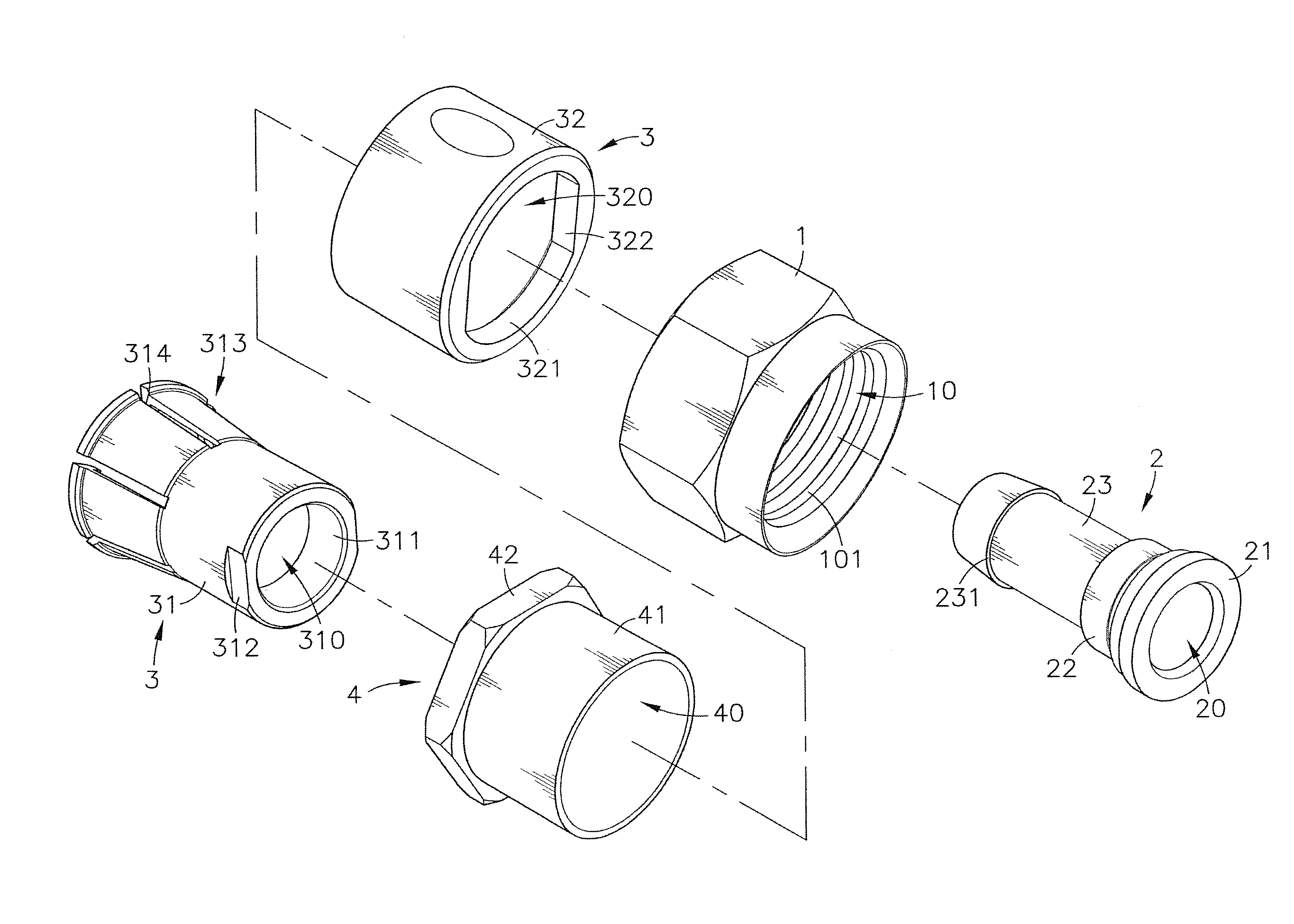
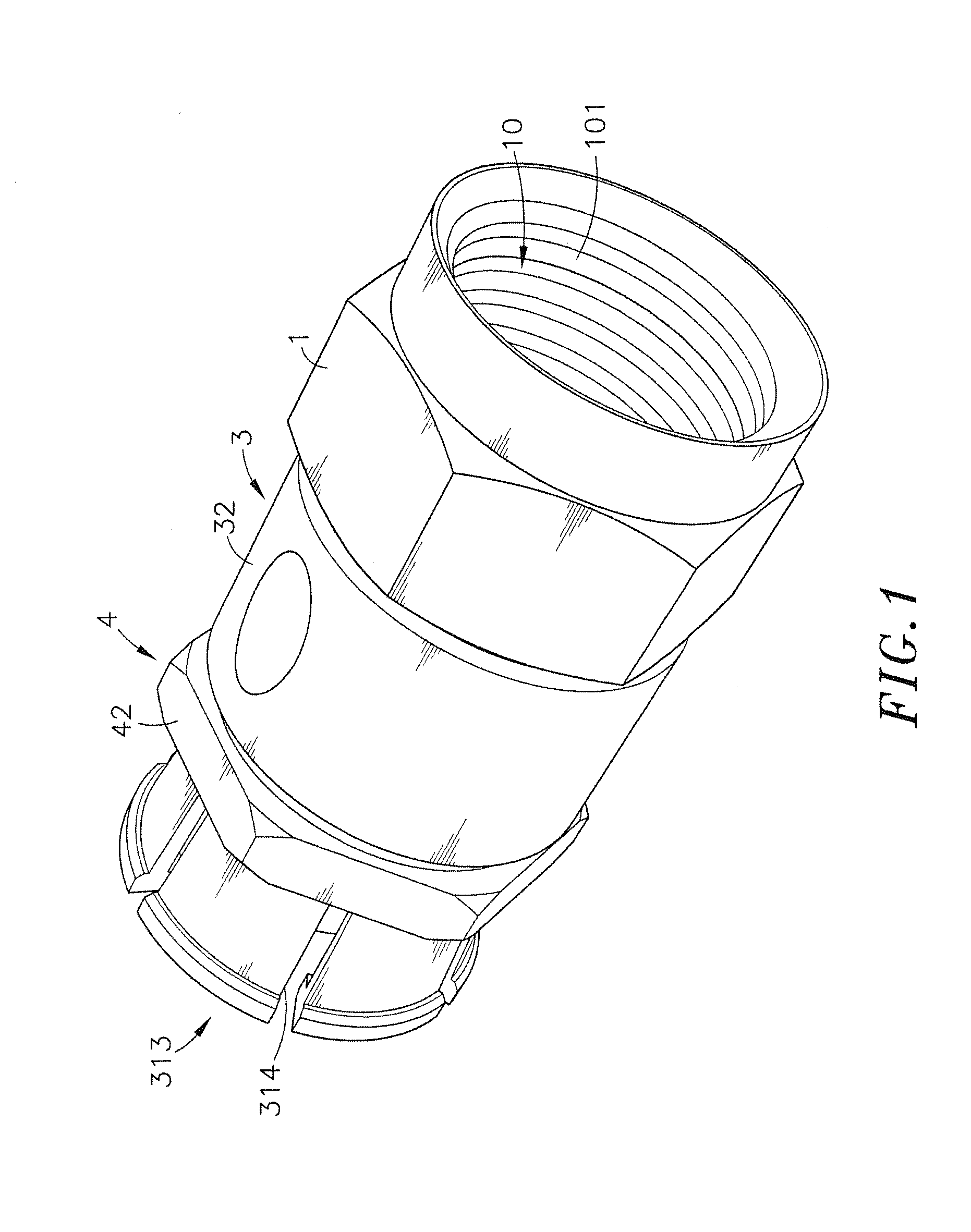
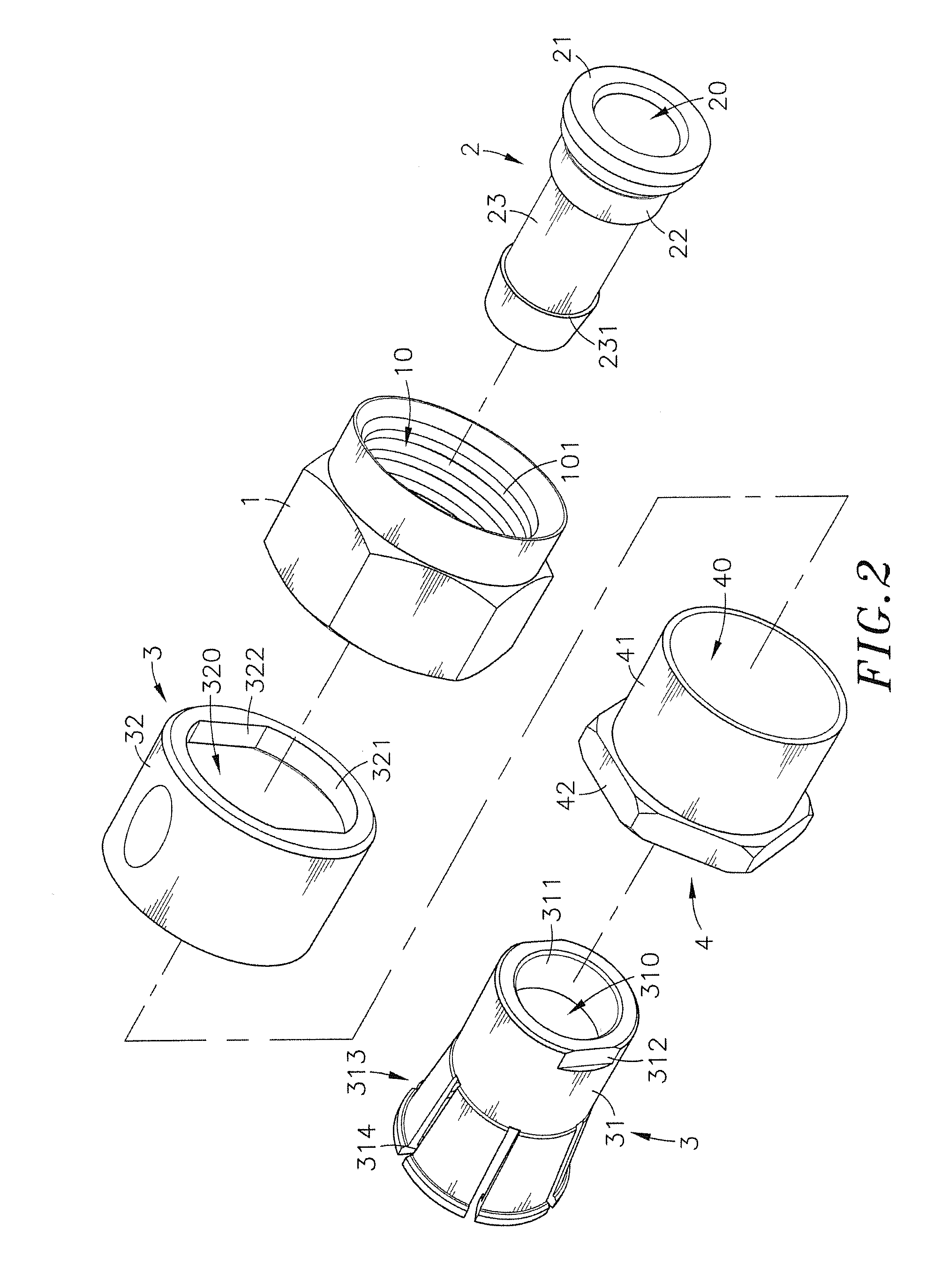
[0018]Referring to FIGS. 1-3, an electrical signal connector in accordance with the present invention is shown comprising a locknut 1, a metal central tube 2, a chuck unit 3, and an actuation sleeve 4.

[0019]The locknut 1 comprises a mating hole 10 extending through two opposing ends thereof, an inner thread 101 disposed in one end of the mating hole 10, and an inside annular flange 11 disposed in an opposite end of the mating hole 10.

[0020]The metal central tube 2 comprises an axial hole 20 axially extending through two opposing ends thereof, a stop flange 21 extending around the periphery thereof at one end, a barbed retaining portion 231 extending around the periphery thereof at the opposite end, a locating groove 23 extending around the periphery between the stop flange 21 and the barbed retaining portion 231, and an annular bearing surface portion 22 extending around the periphery between the stop flange 21 and the locating groove 23.

[0021]The chuck unit 3 comprises a collar 31 ...


PUM


Abstract

An electrical signal connector for connecting a coaxial cable to a mating connector is disclosed to include a locknut, a metal central tube inserted through the locknut and defining a stop flange at one end, a barbed retaining portion at an opposite end, a locating groove around the periphery between the stop flange and barbed retaining portion and an annular bearing surface portion extending around the periphery between the stop flange and the locating groove, a chuck unit including a collar, which is press-fitted onto the annular bearing surface portion of the metal central tube and having longitudinal clamping strips suspending around the barbed retaining portion of the metal central tube, and a constraint shell surrounding the collar, and an actuation sleeve mounted within the constraint shell around the collar and manually axially movable relative to the chuck unit between two positions to compress or release the longitudinal clamping strips.

Description

BACKGROUND OF THE INVENTION[0001]1. Field of the Invention[0002]The present invention is electrical signal connectors and more particularly to an electrical signal connector consisting of a locknut, a metal central tube, a chuck unit and an actuation sleeve, which enables the inserted coaxial cable to be quickly locked to the electrical signal connector by means of manually moving the actuation sleeve relative to the chuck unit without the use of a tool.[0003]2. Description of the Related Art[0004]FIG. 7 illustrates a conventional electrical signal connector (cable end connector) A for connecting a coaxial cable B to a mating connector (not shown). This electrical signal connector (cable end connector) A consists of a locknut A1, a metal central tube A2, a plastic cylindrical casing A3 and a metal barrel A4. The metal central tube A2 is fastened to one end of the locknut A1. The plastic cylindrical casing A3 is fastened to the same end of the locknut A1 around the metal central tube...

Claims


Application Information

Patent Timeline
Patent Type & Authority Patents(United States)
IPC IPC(8): H01R24/38H01R9/05
CPCH01R9/0524
Inventor LEE, CHUNG-YU
Owner LEE CHUNG YU
Why Eureka
Try Eureka