Rotatable power generating plant for producing electric power from water flow

A technology for power generation equipment and electrical energy, which is applied in the directions of hydropower generation, ocean energy power generation, mechanical equipment, etc., and can solve the problems of the formation and enlargement of impossible rotating joints.

Inactive Publication Date: 2009-03-11
VOITH PATENT GMBH
View PDF2 Cites 1 Cited by
  • Summary
  • Abstract
  • Description
  • Claims
  • Application Information

AI Technical Summary

Problems solved by technology

[0006] However, the disadvantage of the known independently rotatable fluid power generators is that, due to the permanently repeated rotational movement, a continuous increase in the degree of twisting of the corresponding part, which is the connection to the fastening element and the resulting The above-mentioned parts themselves cannot be formed by rotating joints

Method used


Image

  • Rotatable power generating plant for producing electric power from water flow
  • Rotatable power generating plant for producing electric power from water flow
  • Rotatable power generating plant for producing electric power from water flow

Examples


Embodiment Construction

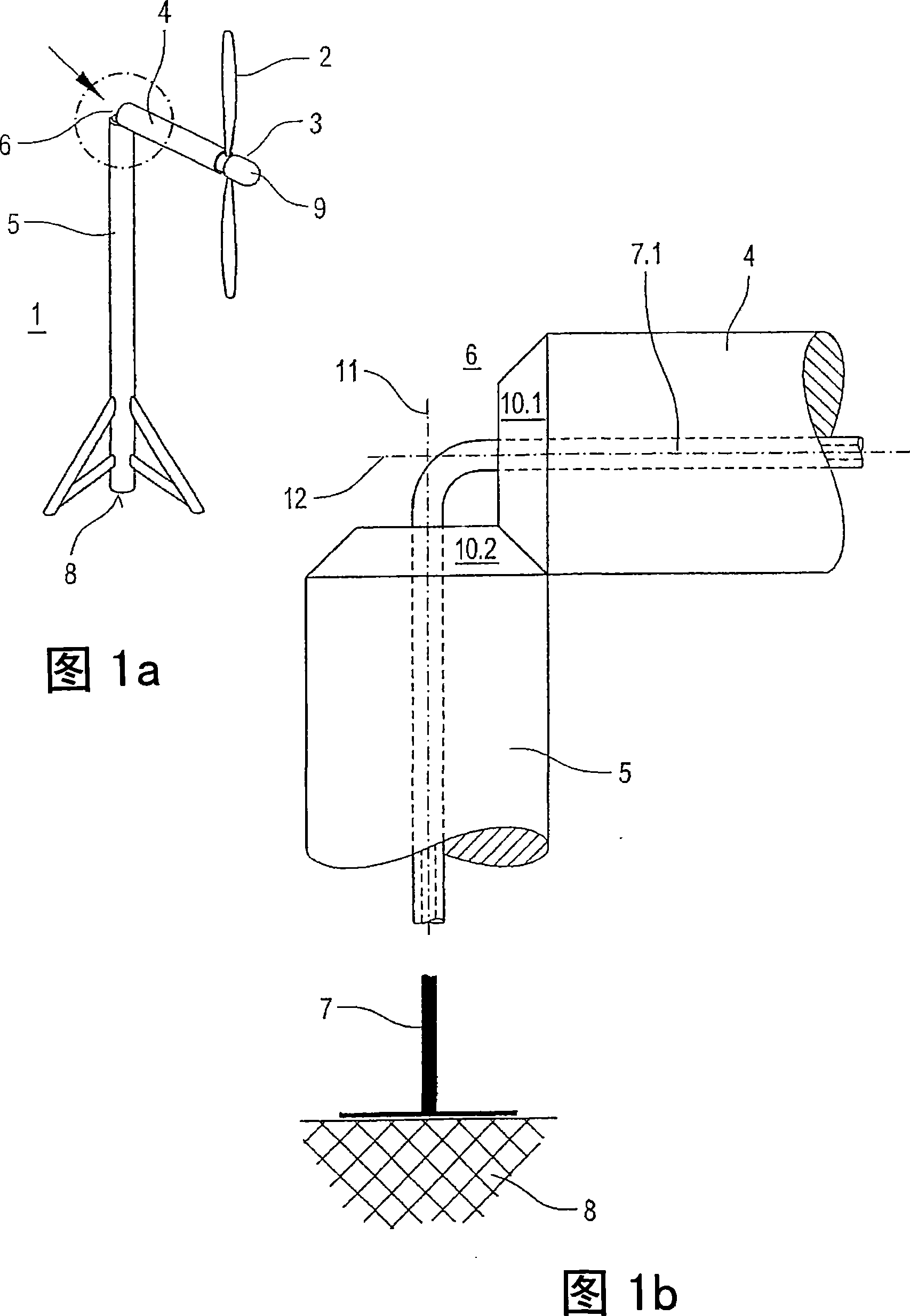
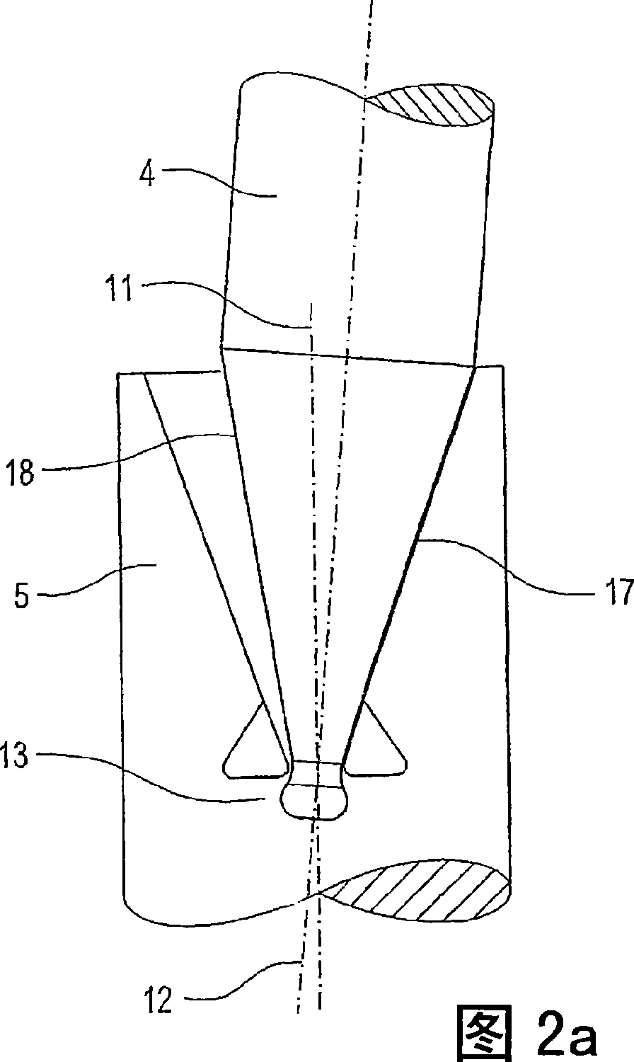
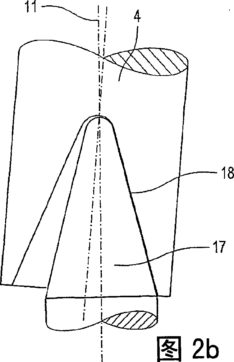
[0023]The basic components of a power plant 1 according to the invention are shown schematically and simplified in FIGS. 1 a and 1 b. A water turbine 2 is used to convert the kinetic energy of the water flow, which can be designed, for example, in the form of a propeller. The water turbine drives a generator 3 which is accommodated in a nacelle 9 or whose housing forms the nacelle. A pod body 4 is assigned to the pod 9 , which is used to distance the water turbine from the support body 5 . The support body 5 can be, for example, a pillar or a grating with anchors on the sea bottom 8 . Alternatively, a floatable unit can be provided as carrier body 5 , which is anchored by thick ropes and thus essentially fixed in position relative to the sea bottom 8 and free from relative rotation. A hinge connection device 6 is arranged between the pod body 4 and the carrier body 5. According to the present invention, the hinge connection device is constituted as follows, so that the activ...


PUM


Abstract

The invention relates to a rotatable generation unit for generating electric energy from a water flow, comprising: a water turbine; an electric generator, driven by the water turbine; a carrier body, wherein a first axis is provided; a nacelle body, with which a second axis, which is angled toward the first axis, is provided and which is moveable relative to the carrier body; a connecting cable, extending from the electric generator through the nacelle body to the carrier body; a hinge connection device between the carrier body and the nacelle body ,possessing a device which transmits a rotational movement of the nacelle body about the first axis into a rotational movement of the nacelle body about the second axis assigned therewith, so that the twisting of the connecting cable is limited.

Description

technical field [0001] The invention relates to a rotatable power plant for obtaining electrical energy from water currents, in particular from ocean currents or flowing water currents. Background technique [0002] Submerged power plants, which are designed independently of the embankment structure and are driven by the kinetic energy of water currents, in particular ocean currents, represent a great potential for exploiting renewable energy sources. Due to the high density of the flow medium, energy can already be harvested economically with relatively low flow velocities of approximately 2 to 2.5 m / s. This flow relationship can either be present as a tidal current or other ocean currents can be used which, in particular, can achieve economical velocities in straits. This flow can drive a hydroelectric power plant, which has a configuration similar to a wind power plant, that is to say uses a runner with rotor blades as a water turbine. However, other turbine concepts su...

Claims


Application Information

Patent Timeline
Patent Type & Authority Applications(China)
IPC IPC(8): F03B13/26F03B17/06H02G11/00
CPCF05B2260/4031F03B11/00E02B2017/0091F05B2260/40F05B2240/14F05B2250/192F03B13/264Y02E10/28F03B17/061F05B2250/42F05B2240/97H02G11/00Y02E10/30F03B13/26F03B17/06Y02E10/20
Inventor N·佩纳B·荷尔斯泰因
Owner VOITH PATENT GMBH
Why Eureka
Try Eureka