
Device and method for decreasing energy consumption of a person by use of a lower extremity exoskeleton

a technology of lower extremity and exoskeleton, which is applied in the field of lower extremity exoskeleton, can solve the problems of increasing the oxygen consumption of the wearer, not being able to transfer power from the exoskeleton to the person, and people of ordinary ability often consume a great deal of energy

Active Publication Date: 2015-02-03
EKSO BIONICS
View PDF40 Cites 40 Cited by
  • Summary
  • Abstract
  • Description
  • Claims
  • Application Information

AI Technical Summary

Benefits of technology

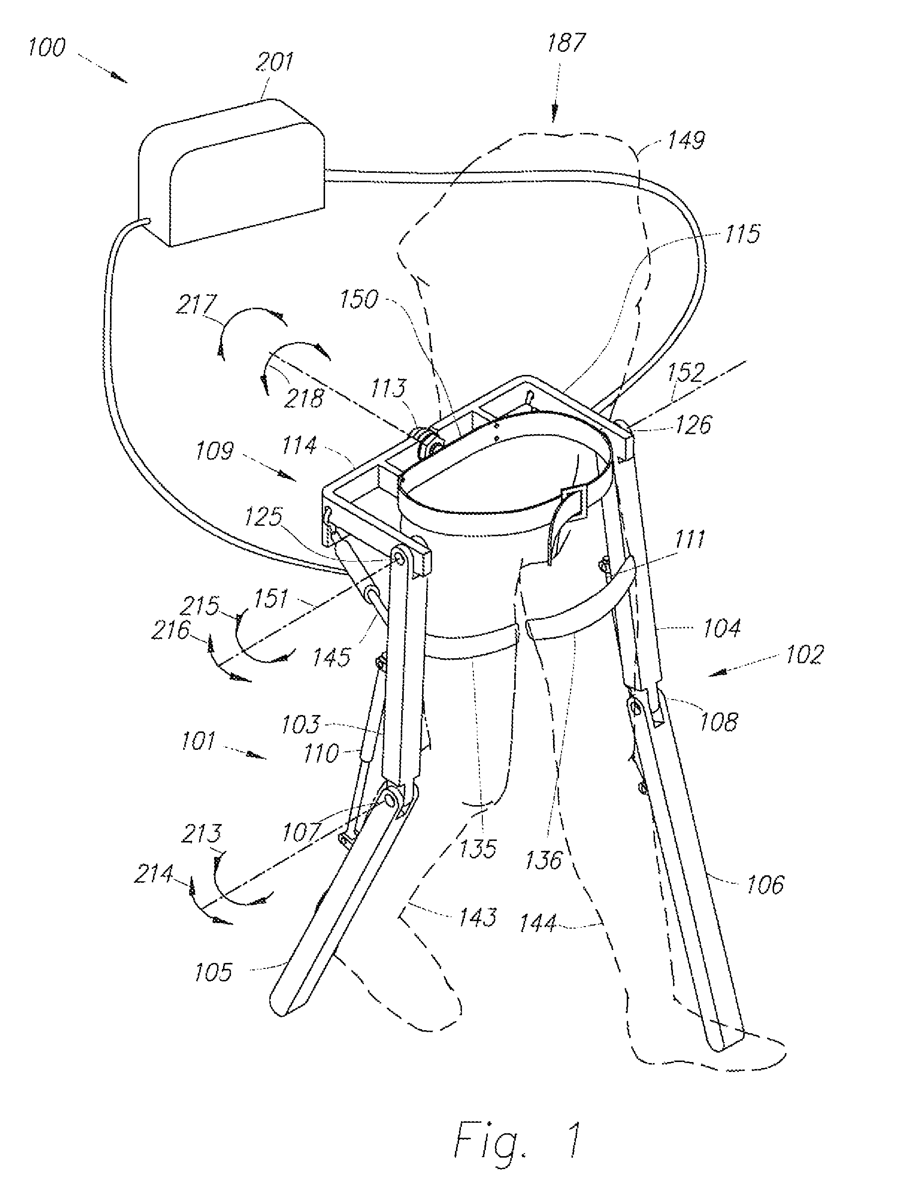
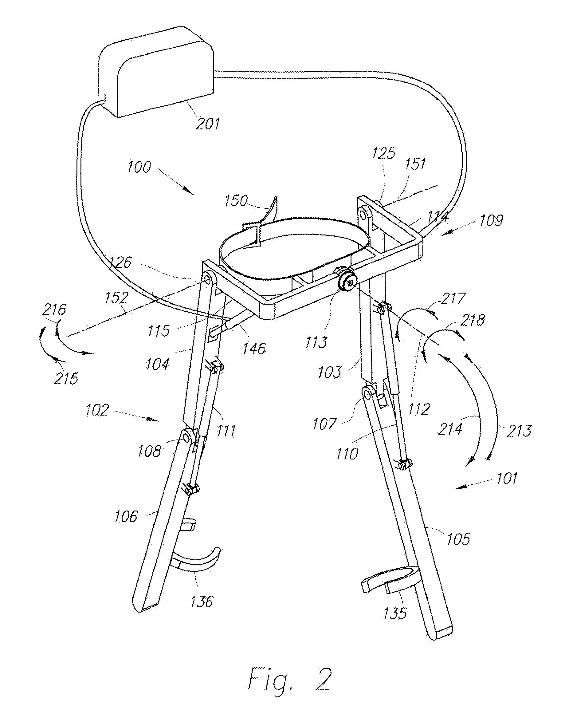
The patent describes a lower extremity exoskeleton that can be worn by a person to provide support and mobility. The exoskeleton includes leg supports, knee joints, an exoskeleton trunk, hip actuators, and a power unit. When the person wears the exoskeleton, the power unit provides energy to the hip actuators to create a torque profile that helps the person walk more confidently and comfortably. The technical effect of this invention is to provide a wearable exoskeleton that improves mobility and stability for people with mobility issues.

Problems solved by technology

In a wide variety of situations, people of ordinary ability often consume a great deal of energy when walking or carrying a load.
However, the quasi-passive exoskeleton taught by Walsh et al. increases its wearer's oxygen consumption.
More specifically, the exoskeleton described has no actuation and power unit and therefore will not be able to transfer power from the exoskeleton to the person.
However, the “get out of the way” control method will not reduce a wearer's energy expenditure because the force from the exoskeleton onto the wearer is in the opposite direction to the wearer's motion and in fact increases the wearer's energy expenditure.

Method used


Image

  • Device and method for decreasing energy consumption of a person by use of a lower extremity exoskeleton
  • Device and method for decreasing energy consumption of a person by use of a lower extremity exoskeleton
  • Device and method for decreasing energy consumption of a person by use of a lower extremity exoskeleton

Examples


case 1

[0089]As can be examined from equation (9) if hip actuator torque TE is such that:

TE>(MTRUNKL2+I){umlaut over (β)}1−(LMTRUNK+RML)g Sin(β1+α)+TF  (10)

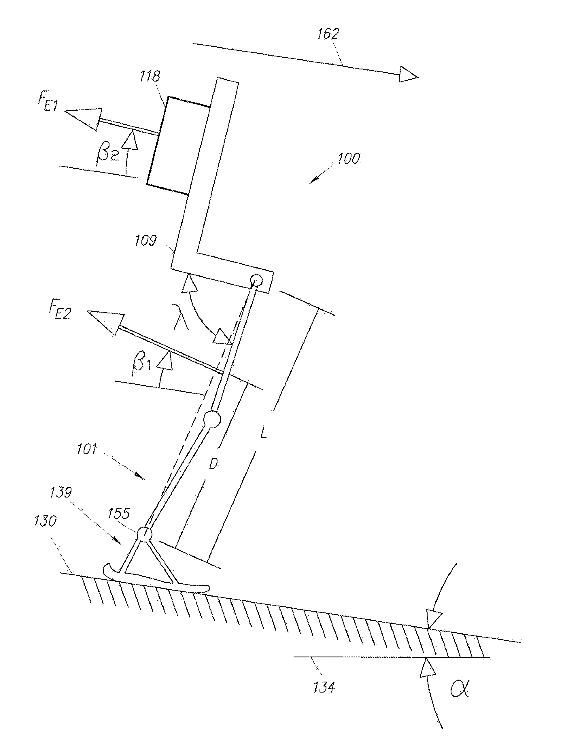
Then FE1L Cos(β2−β1)+FE2D>0. This means if the actuator torque is chosen such that it is larger than the summation of the inertial torque (MTRUNKL2+I){umlaut over (β)}1, gravitational torque −(LMTRUNK+RML)g Sin(β1+α), and the frictional torque TF, then the torque from person 187 onto lower extremity exoskeleton 100 about point F, FE1L Cos(β2−β1)+FE2 D, is positive. This means that the torque from person 187 on lower extremity exoskeleton 100 is in the counterclockwise direction and the torque on person 187 is in the clockwise direction and along the person's forward velocity direction 162. When the torque on person 187 is along the person's forward velocity direction 162 (as shown in FIG. 5), power is transferred from lower extremity exoskeleton 100 to person 187. Since the time integral of this power over the entire stance time is posi...

case 2

[0091]As can be examined from equation (9) if the hip actuator torque, TE is such that:

TEMTRUNKL2+I){umlaut over (β)}1−(LMTRUNK+RML)g Sin(β1+α)+TF  (11)

[0092]Then FE1L Cos(β2−β1)+FE2DTRUNKL2+I){umlaut over (β)}1, gravitational torque −(LMTRUNK+RML)g Sin(β1+α), and the frictional torque TF, then the torque from person 187 onto lower extremity exoskeleton 100 about point F, FE1L Cos(β2−β1)+FE2D is negative. This means that the torque from person 187 on lower extremity exoskeleton 100 about point F is in the clockwise direction and the torque on person 187 is opposite to the person's forward velocity direction 162 (counterclockwise direction). When the torque on person 187 is opposite to the person's forward velocity direction 162 (as shown in FIG. 5), power is transferred from person 187 to lower extremity exoskeleton 100. If the time integral of this power over the entire stance time is negative, mechanical energy is transferred to lower extremity exoskeleton 100 from person 187.

case 3

[0093]As can be examined from equation (9), if the hip actuator torque TE is such that:

TE=(MTRUNKL2+I){umlaut over (β)}1−(LMTRUNK+RML)g Sin(β1+α)+TF  (12)

Then FE1L Cos(β2−β1)+FE2D=0. This means the torque from person 187 onto lower extremity exoskeleton 100 about point F is zero. If the time integral of this power over the entire stance time is zero, no mechanical energy is transferred between lower extremity exoskeleton 100 and person 187. In this case, the wearer's energy expenditure neither increases nor decreases.

Remark 1

[0094]Since exoskeleton trunk 109 rotates very little (i.e., β2 is relatively constant in comparison to angle λ) and the summation of torques on exoskeleton trunk 109 is zero, equation (13) states that the torque on exoskeleton trunk 109 from person's upper body cancels the algebraic summation of the reaction torques from hip actuators 145 and 146.

TP=TE−TS−TG  (13)

where:[0095]TP: Torque on exoskeleton trunk 109 from person's upper body 149[0096]TE: Torque on exo...


PUM


Abstract

A lower extremity exoskeleton, configurable to be coupled to a person, includes: leg supports configurable to be coupled to the person's lower limbs and designed to rest on the ground during stance phases, with each leg support having a thigh link and a shank link; two knee joints, each configured to allow flexion and extension between respective shank and thigh links; an exoskeleton trunk configurable to be coupled to the person's upper body, rotatably connectable to the thigh links of the leg supports, allowing for the flexion and extension between the leg supports and the exoskeleton trunk; two hip actuators configured to create torques between the exoskeleton trunk and the leg supports; and at least one power unit capable of providing power to the hip actuators. In use, power is supplied to the hip actuators in an amount to reduce the energy consumed by a user during a walking cycle.

Description

CROSS-REFERENCE TO RELATED APPLICATIONS[0001]This application claims the benefit of U.S. Provisional Application No. 61 / 071,823 entitled DEVICE AND METHOD FOR DECREASING ENERGY CONSUMPTION OF A PERSON BY USE OF A LOWER EXTREMITY EXOSKELETON, filed May 20, 2008.BACKGROUND OF THE INVENTION[0002]1. Field of the Invention[0003]The present invention relates generally to the field of lower extremity exoskeletons and, more particularly, to the field of lower extremity exoskeletons that decrease their wearer's energy consumption.[0004]2. Discussion of the Prior Art[0005]In a wide variety of situations, people of ordinary ability often consume a great deal of energy when walking or carrying a load. One attempt to improve load carrying ability is set forth in the paper entitled “A QUASI-PASSIVE LEG EXOSKELETON FOR LOAD-CARRYING AUGMENTATION”, C. J. Walsh, K. Endo, and H. Herr, International Journal of Humanoid Robotics, 2007. However, the quasi-passive exoskeleton taught by Walsh et al. incre...

Claims


Application Information

Patent Timeline
Patent Type & Authority Patents(United States)
IPC IPC(8): A61H3/00A61H3/06B25J9/00
CPCA61H3/061B25J9/0006A61H3/008A61H3/00
Inventor KAZEROONI, HOMAYOONAMUNDSON, KURTHARDING, NATHAN
Owner EKSO BIONICS
Learn More