Belt connector and method

Active Publication Date: 2015-02-03
MATO MASCH & METALLWARENFABRIK CURT MATTHAEI GMBH & CO KG
View PDF18 Cites 2 Cited by
  • Summary
  • Abstract
  • Description
  • Claims
  • Application Information

AI Technical Summary

Benefits of technology

[0012]One object of the present invention is to ensure durable and wear-resistant attachment of the cover element to the belt in a connection of the type cited in the foregoing. Another object of the present invention is to provide a method th

Problems solved by technology

Producing such a connection is very complex because vulcanization is required in order to apply the rubber cover layers.
Joining such belts in the manners described above is very complex,

Method used


Image

  • Belt connector and method
  • Belt connector and method
  • Belt connector and method

Examples


Embodiment Construction

[0046]For purposes of description herein, the terms “upper”, “lower”, “right”, “left”, “rear”, “front”, “vertical”, “horizontal” and derivatives thereof shall relate to the invention as oriented in FIGS. 1 and 4. However, it is to be understood that the invention may assume various alternative orientations and step sequences, except where expressly specified to the contrary. It is also to be understood that the specific devices and processes illustrated in the attached drawings, and described in the following specification, are simply exemplary embodiments of the inventive concepts defined in the appended claims. Hence, specific dimensions and other physical characteristics relating to the embodiments disclosed herein are not to be considered as limiting, unless the claims expressly state otherwise.

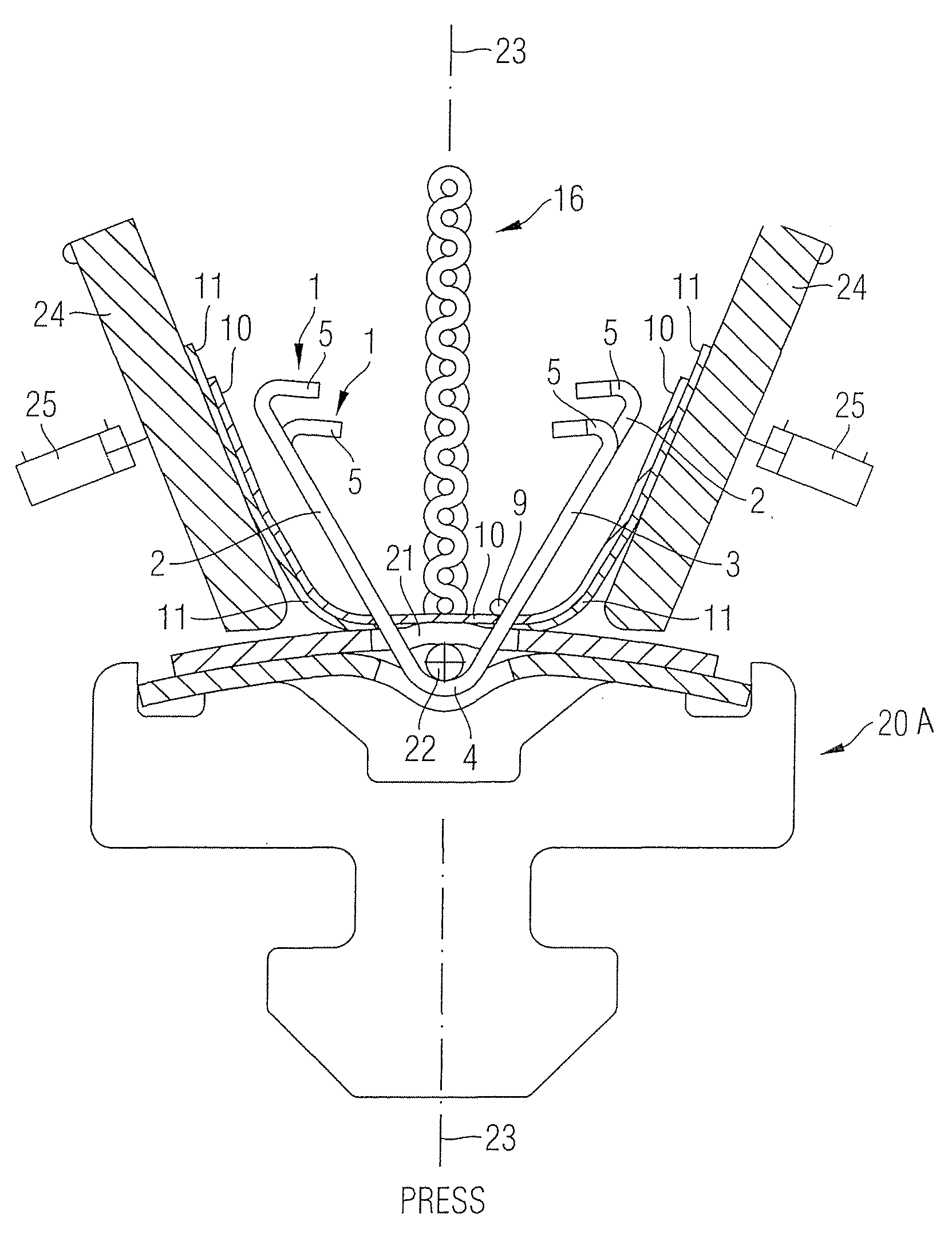
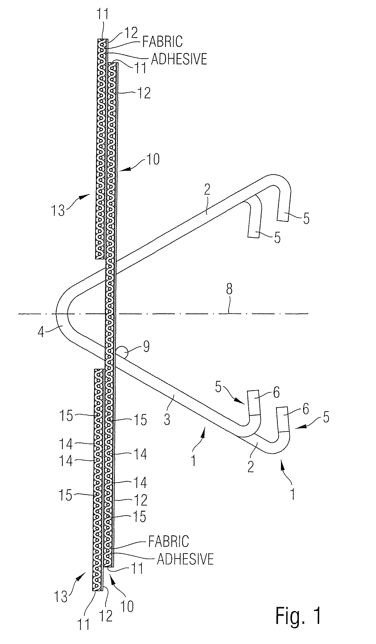
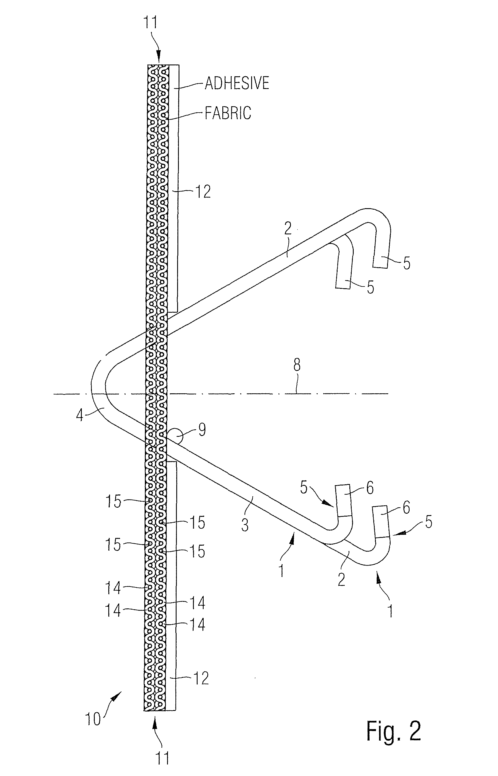
[0047]For the first embodiment, FIGS. 1, 3, and 4 depict a belt connector assembly having a plurality of wire hooks 1. Each wire hook 1 has a long shank 2 and a short shank 3, as well as ...


PUM

PropertyMeasurementUnit
Pressureaaaaaaaaaa
Pressureaaaaaaaaaa
Pressureaaaaaaaaaa

Abstract

A belt connector and method for interconnecting opposite ends of a filtering belt has a plurality of wire hooks, each with two shanks disposed adjacent opposite faces of the belt, a coupling loop interconnecting the shanks and hook ends that are pressed into the opposite faces of the belt. A flat cover element extends across the width of the belt, covers at least portions of the wire hooks, overlies the opposite faces of the belt, and has a carrier material and a coating that is applied to the belt side of the carrier material, and is constructed from a thermoplastic or an adhesive material which is pressed into the pores of the belt to positively and mechanically interconnect the cover element with the belt.

Description

CLAIM OF PRIORITY[0001]Applicant hereby claims the priority benefits under the provisions of 35 U.S.C. §119, basing said claim of priority on PCT / EP20009 / 003344, claiming priority to EPC 080093586, filed May 21, 2008. In accordance with the provisions of 35 U.S.C. §119 and Rule 55(b), a certified copy of the above-listed EPC patent application will be filed before grant of a patent.BACKGROUND OF THE INVENTION[0002]The present invention relates to belt connectors of the type having wire hooks to interconnect the opposite ends of a belt. Each wire hook has two shanks arranged on opposite sides of the belt, and furthermore has hook ends adjoining the shanks, wherein the hook ends are pressed into the carcass of the belt. Each wire hook also has a coupling loop connecting the two shanks. The belt connector furthermore has a flat cover element that extends on both sides of the belt to cover portions of the hook assembly. The cover element extends across the width of the belt, and has a c...

Claims


Application Information

Patent Timeline
IPC IPC(8): A41H37/00B32B37/00B29C65/00B32B7/08A44B19/00B65G17/00F16G3/00F16G3/04
CPCF16G3/04F16G3/003Y10T24/33Y10T156/109
Inventor HEROLD, WOLFGANG
Owner MATO MASCH & METALLWARENFABRIK CURT MATTHAEI GMBH & CO KG
Why Eureka
Try Eureka