Car power source apparatus

Active Publication Date: 2011-01-13
SANYO ELECTRIC CO LTD
View PDF6 Cites 26 Cited by
  • Summary
  • Abstract
  • Description
  • Claims
  • Application Information

AI Technical Summary

Benefits of technology

[0018]This power source apparatus can also effectively prevent water ingress into the case and effectively prevent corrosion and electrical shock by making the case, which houses the battery blocks and battery state detection section, water-tight with an extremely simple structure. Further, the top cover attaches to the battery blocks in a reliable water-tight configuration that allows the top cover to be detached from the battery blocks. This is because the top cover is attached to the battery block attachment section via set screws, and the battery block attachment section is provided with attachment surfaces that contact the inside surface of the top cover. The attachment surfaces are provided with screw-holes, which have bottoms that are closed-off, and ring-shaped gaskets are disposed around the outsides of the screw-holes. Further, the gaskets are sandwiched between the top cover and the attachment surfaces to attach the top cover to the battery blocks in a water-tight structure.
[0019]In the car power source apparatus of the present invention, the battery blocks 2 have a plurality of batteries 1 stacked and held between endplates 22, and the battery block 2 attachment section 9 can be an attachment bar 31 that extends lengthwise in the battery 1 stacking dire

Problems solved by technology

This is necessary because water ingress into the case can corrode the batteries and internal metal components.
In addition, water ingress into the case can also be the cause of leakage currents and electrical shocks.
However, it is difficult to reliably sandwich the gaskets 95 for this water-tight structure, and it has the drawback that long-

Method used


Image

  • Car power source apparatus
  • Car power source apparatus
  • Car power source apparatus

Examples


Example

[0038]The following describes embodiments of the present invention based on the figures. However, the following embodiments are merely specific examples of a car power source apparatus representative of the technology associated with the present invention, and the car power source apparatus of the present invention is not limited to the embodiments described below.

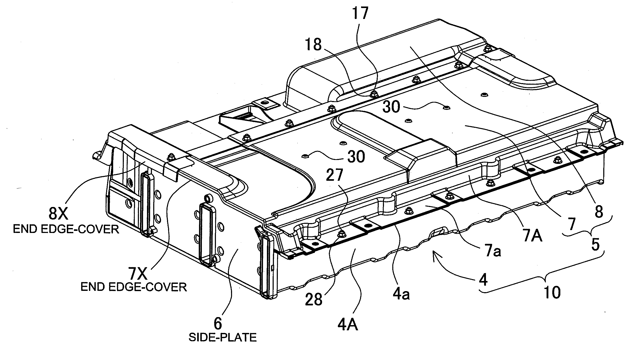
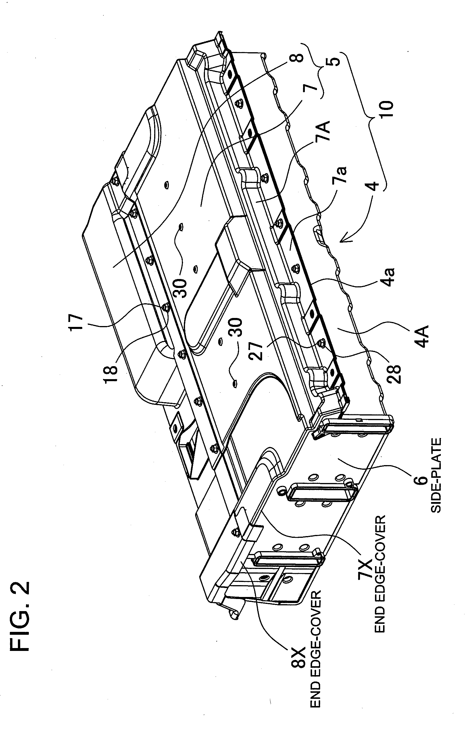
[0039]The car power source apparatus shown in FIGS. 2-6 is provided with battery blocks 2 having a plurality of connected batteries 1; a battery state detection section 3 connected to the battery blocks 2; a base-plate 4 that has the battery state detection section 3 and battery blocks 2 mounted on top; a cover-plate 5 that closes-off the top of the base-plate 4, establishes a battery holding region 12 that holds the battery blocks 2 between the base-plate 4 and the cover-plate 5, and establishes an electronic component compartment 13 that houses the battery state detection section 3; and side-plates 6 that close-off the o...


PUM


Abstract

The car power source apparatus has battery block 2 having a plurality of connected batteries 1, a battery state detection section 3 connected to the battery block 2, a base-plate 4 having the battery state detection section and battery block mounted on top, a cover-plate 5 that closes-off the top of the base-plate 4, and side-plates 6 that close-off the open regions between the cover-plate 5 and base-plate 4 at both ends. The cover-plate 5 is provided with a top cover 7 that establishes the battery holding region 12 inside, and an electronic component cover 8 that establishes the electronic component compartment 13 inside. The edges at both ends of the cover-plate 5 have end edge-covers 7X, 8X that extend downward from the side-plate 6 top surfaces down the outer surfaces. The end edge-covers 7X, 8X make the connection between the cover-plate 5 and the side-plates 6 a water-tight structure.

Description

BACKGROUND OF THE INVENTION[0001]1. Field of the Invention[0002]The present invention relates to a high-current power source apparatus primarily used as the power source for a motor that drives an automobile such as a hybrid car or electric vehicle (EV), and in particular to a power source apparatus that prevents the ingress of water into the case that houses the batteries.[0003]2. Description of the Related Art[0004]An automobile such as an electric vehicle driven by a motor or a hybrid car driven by both a electric motor and an engine has a power source apparatus with a case housing batteries installed on-board. Since the vehicle is driven by an electric motor, the power source apparatus has many batteries connected in series to increase the voltage for large output. For example, although the voltage for a standard automobile electric system battery (lead-acid storage battery) installed in most cars is almost without exception 12V, the output voltage of a power source apparatus th...

Claims


Application Information

Patent Timeline
IPC IPC(8): H01M10/48H01M50/209H01M50/24H01M50/262H01M50/264H01M50/271
CPCH01M2/1077H01M10/48H01M10/425Y02E60/10H01M50/209H01M50/264H01M50/24H01M50/262H01M50/271
Inventor OKADA, WATARUNAKAMURA, SHINSUKEWAKABAYASHI, AKINOBU
Owner SANYO ELECTRIC CO LTD
Why Eureka
Try Eureka