Wind-tracking twin-turbine system

a twin-turbine, wind-tracking technology, applied in the direction of electric generator control, renewable energy generation, greenhouse gas reduction, etc., to achieve the effect of reducing air resistance, increasing flight distances, and improving the adhesion of boundary layers

Active Publication Date: 2015-02-03
DIRECTTECH GLOBAL GMBH
View PDF20 Cites 12 Cited by
  • Summary
  • Abstract
  • Description
  • Claims
  • Application Information

AI Technical Summary

Benefits of technology

[0016]Golf balls have a large number of small depressions on the surface, known as dimples. As turbulators, they improve the adhesion of the boundary layer that lies against the ball and is entrained by the rotation thereof. This increases the formation of turbulence and the associated deviation of the ball due to the Magnus effect. Since the golf ball rotates backward as a result of the wedge shape of the golf club, it is lifted by the Magnus effect; it does not simply fly like a cannonball, but instead experiences lift. Additional deviations to the left or right are possible, and are also used by players who have mastered this technique. Moreover, the supercritical turbulent circulation reduces the air resistance, and this in turn leads to greater flight distances.
[0017]According to the invention, high performance is achieved in combination with low installation costs in such a way that the cost-effectiveness in terms of power output is much greater than in the known wind-powered generators comprising a horizontal shaft and blades of the aircraft-wing type.
[0018]To increase the cost-effectiveness, a ring generator is provided for power generation. In addition, to increase the cost-effectiveness further, the mast and the wind splitter can be used as advertising space.
[0019]By contrast with the known wind-powered generators comprising a horizontal shaft and three blades, the radial turbine according to the invention can be operated even at relatively low wind speeds. As a result of the Magnus effect, the radial turbine according to the invention “pulls” the wind in, as it were, and amplifies low wind speeds. For example, the radial turbine according to the invention can also be used in circulating winds, in which the wind speed is greater below at a low height than when at the considerable height at which the three-blade wind-powered generators have to be operated simply because of the blade size. A wind speed that is too low for the known three-blade turbines in any case is sufficient for energy production with the radial turbine according to the invention.

Problems solved by technology

This results in “deflection” of the roller, pushing the roller downward (see FIG. 4).

Method used


Image

  • Wind-tracking twin-turbine system
  • Wind-tracking twin-turbine system
  • Wind-tracking twin-turbine system

Examples


Embodiment Construction

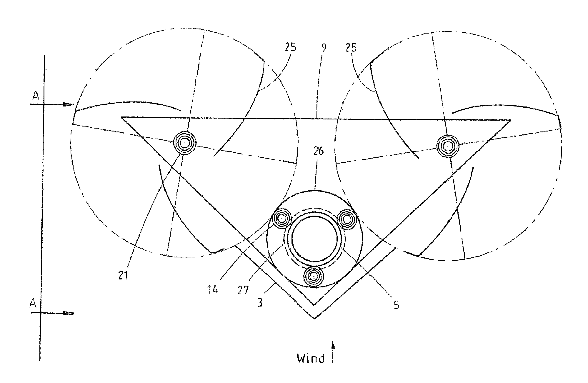
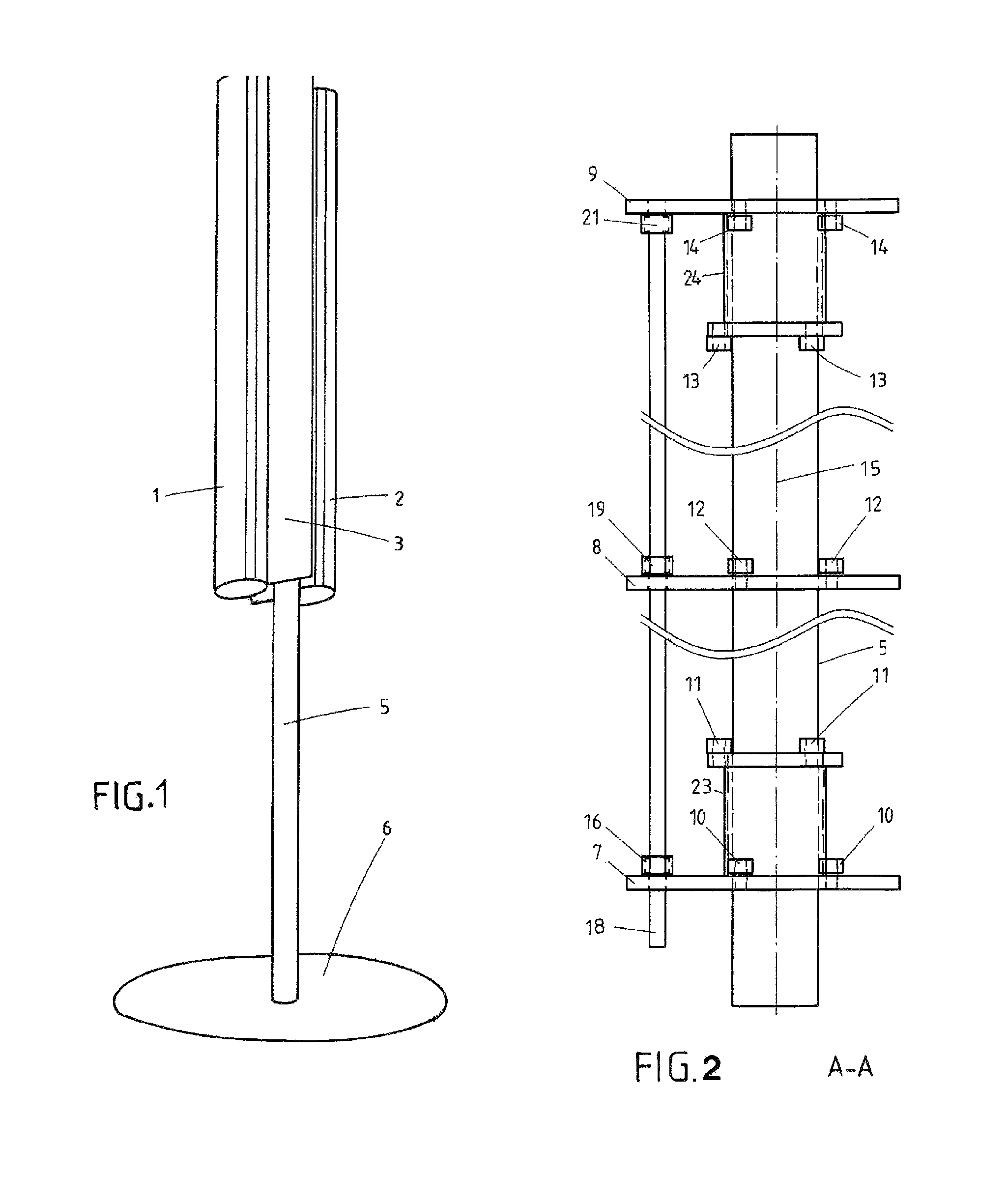
[0034]FIG. 1 is a perspective drawing of the wind-powered generator according to the invention, comprising two radial turbines 1, 2 and a V-shaped wind splitter 3, the radial turbines and wind splitter being attached to a steel mast 5 or another base part 6 so as to be rotatable (pivotable) as a whole about a vertical axis.

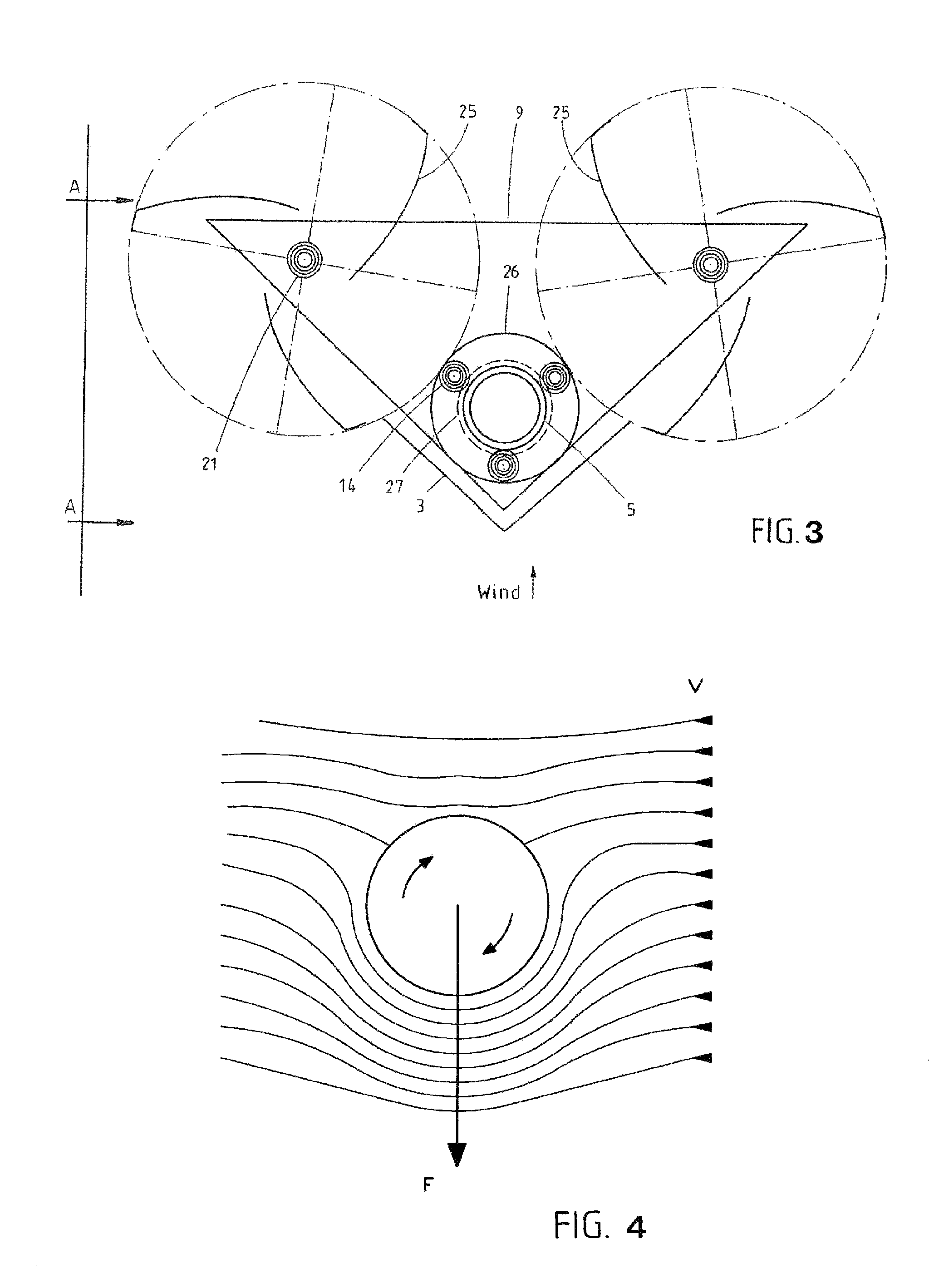
[0035]The efficiency of the wind-powered generator is substantially dependent on the position of the V-shaped wind splitter 3, based on the distance and inclination to the turbine blades and the turbine shaft. The wind-powered generator is additionally advantageously technically equipped such that, according to the wind speed, the optimum position of the wind splitter 3 can be set. The setting can take place on the one hand as a fixed setting for the average (most probable) wind speed; on the other hand, it is also possible to automatically reset to the optimum position based on the current wind speed.

[0036]For an overall height of 20 m, the height of the turbines...


PUM


Abstract

A turbine system for wind and / or water power is characterized in that two radial turbines (1, 2) aligned next to each other and in parallel are arranged having a vertical axis of rotation, said radial turbines being connected to each other and being pivotable about a pivot axis (3) parallel to the turbine axes (18), wherein the pivot axis and a V-shaped wind distributor (3) are located outside the connecting line between the turbine axes and both on the same side of the connecting line.

Description

CROSS REFERENCE TO RELATED APPLICATIONS[0001]This application is the US-national stage of PCT application PCT / EP2011 / 006062 filed 3 Dec. 2011 and claiming the priority of German patent application 102010054365.9 itself filed 13 Dec. 2010, German patent application 102011010177.2 itself filed 2 Feb. 2011, and German patent application 102011109217.3 itself filed 3 Aug. 2011.FIELD OF THE INVENTION[0002]The invention relates to a turbine system comprising two radial turbines.PRIOR ART[0003]By comparison with the known three-blade wind-powered generators having a horizontal axis of rotation and aircraft-type blades, a radial turbine has the major advantage of operating independently of the direction of the incident wind. Thus, the radial turbine having a vertical axis of rotation does not have to be turned to the wind.[0004]In a particularly economical embodiment, the radial turbine is provided with deflector plates that collect the wind energy and deflect it onto the blades of the radi...

Claims


Application Information

Patent Timeline
Patent Type & Authority Patents(United States)
IPC IPC(8): F03B13/00H02P9/04F03D3/00F03D3/06H02K7/18
CPCF03D3/065F03D3/005H02K7/1823F05B2210/16F05B2240/213F05B2240/217F05B2240/40Y02B10/30Y02E10/74F03D3/062F03D3/02F03D3/04F03D3/06
Inventor STEEL, DENNIS PATRICK
Owner DIRECTTECH GLOBAL GMBH
Why Eureka
Try Eureka