Piezoelectric polymer fibers

a polymer fiber and piezoelectric technology, applied in the field of piezoelectric fibers, can solve the problems of mechanical fatigue, high cost and brittle materials, and the failure of efforts to find new piezoelectric materials since then,

Active Publication Date: 2015-02-03
THE JOHN HOPKINS UNIV SCHOOL OF MEDICINE
View PDF17 Cites 10 Cited by
  • Summary
  • Abstract
  • Description
  • Claims
  • Application Information

AI Technical Summary

Benefits of technology

[0014]An embodiment of the current invention provides piezoelectric fibers comprising a polypeptide, wherein molecules of the polypeptide have electric dipole moments that are aligned such that the piezoelectric fiber provides a piezoelectric effect.

Problems solved by technology

They tend to be expensive and brittle materials.
Efforts since then to find new piezoelectric materials generally have met with disappointment.
Mechanical fatigue is also a problem with PVDF.
LDPP has a couple inherent problems that will likely limit its ultimate application in transducers.
First, it loses its piezoelectric function starting at about 50° C. This means that the material is inappropriate for any use that will cause significant warming (potentially any operation in air, for instance).
Second, at high pressures, it is likely the relatively low stiffness of the air voids compared to the polymer will result in collapse of the voids, possibly with discharging.
Thus it is not appropriate for high pressure use.
While it is possible to make piezoelectric microphones from BaTiO3 and PZT, they are generally less sensitive and more expensive than electret microphones.

Method used


Image

  • Piezoelectric polymer fibers
  • Piezoelectric polymer fibers
  • Piezoelectric polymer fibers

Examples


example 1

Preparation of Piezoelectric Fibers

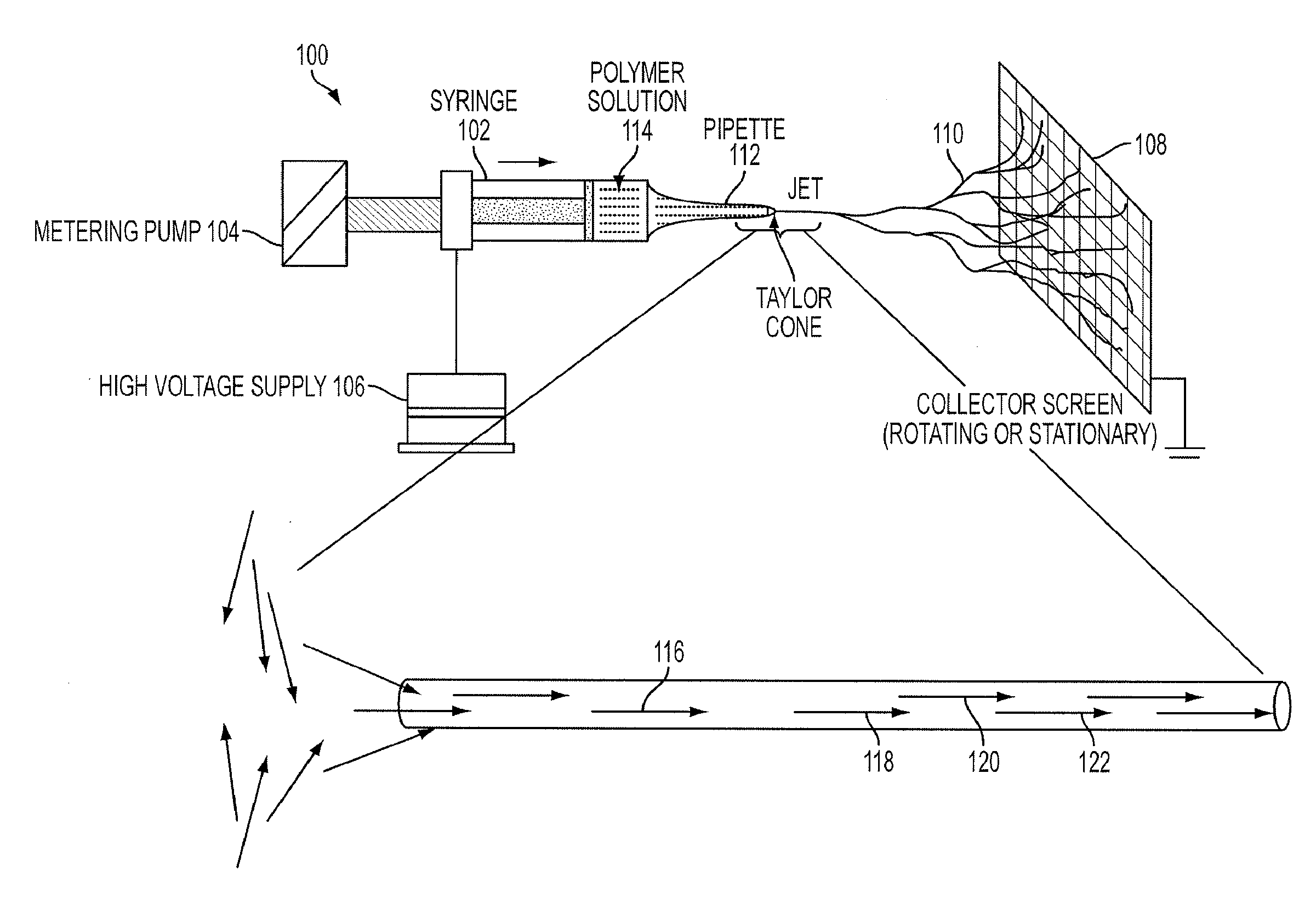
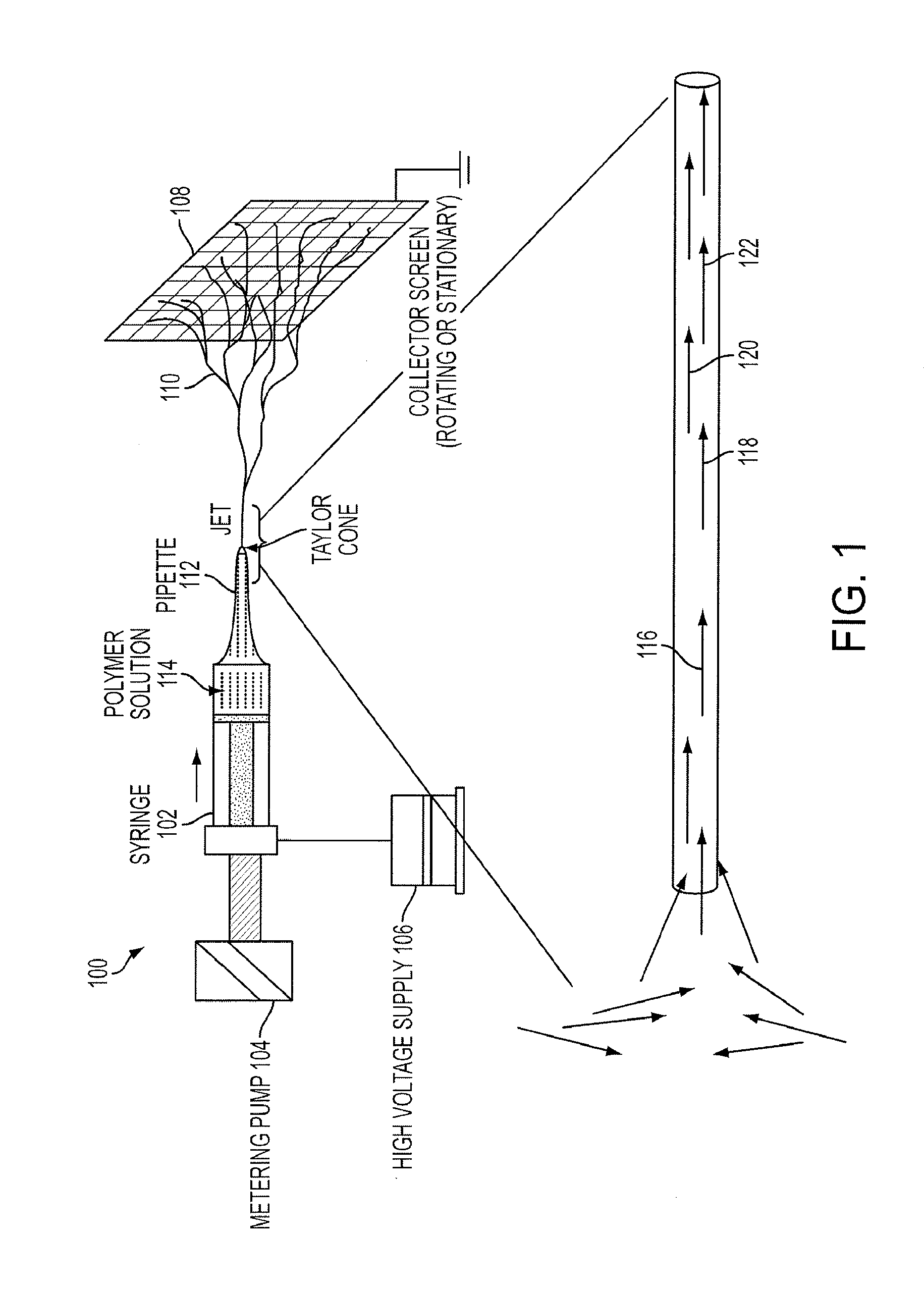
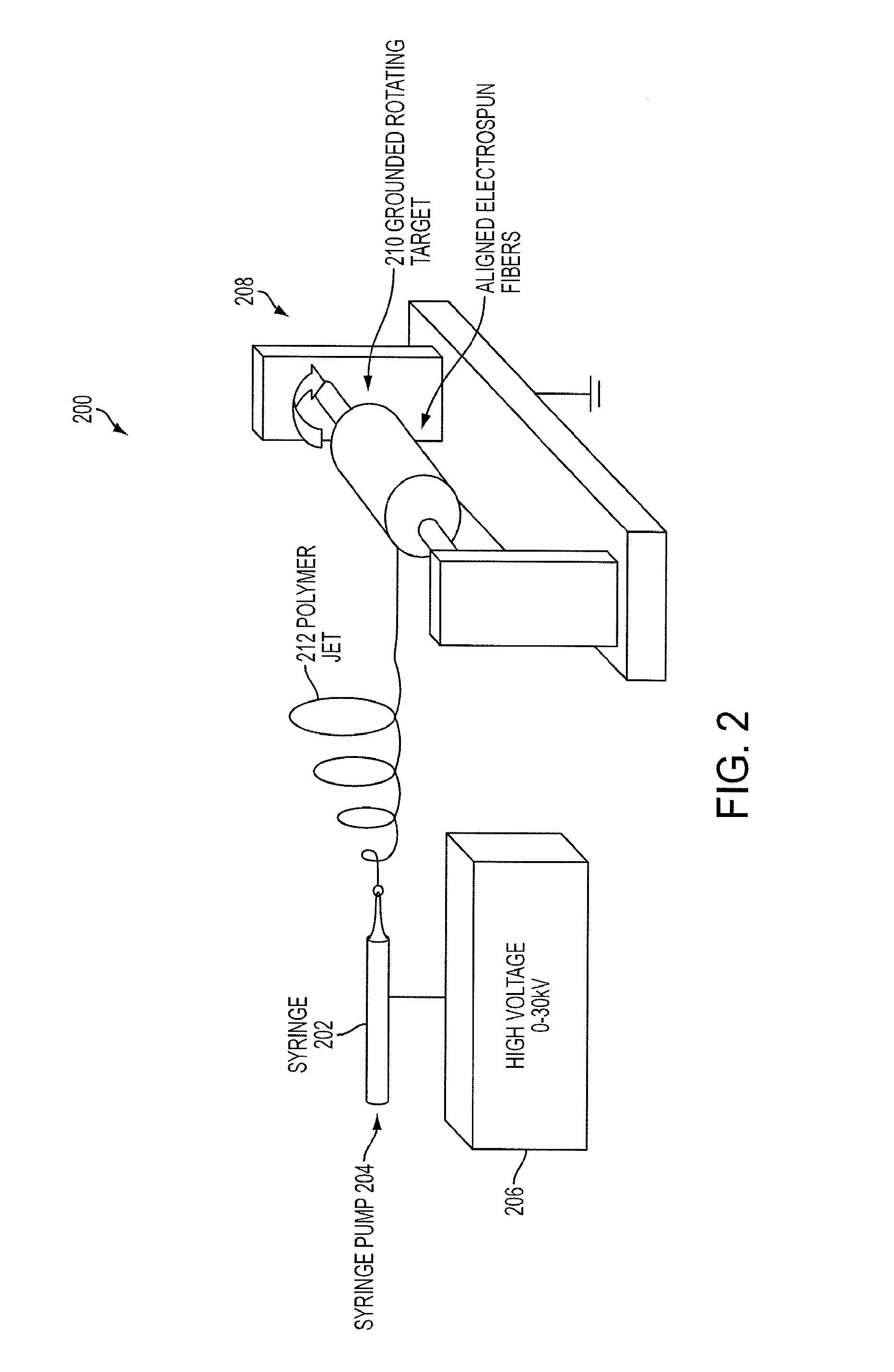
[0081]An electrospinning apparatus is used to prepare the piezoelectric fibers as shown in (FIG. 2). PBLG (DP=760) is dissolved in dichloromethane to a concentration of 8-10% and the resulting solution is transferred to a syringe. After applying a voltage of 15 kV (using the power supply), the solution is slowly forced out of the needle of syringe at a rate of 2 mL / hr (±0.5 mL / hr depending on concentration) by pushing the plunger. The solution is jetted toward the target. During the flight, the solvent evaporates and solid fibers where the dipole moments of the PBLG are aligned (FIG. 12) are collected at the substrate. When a stationary substrate is used, fibers are randomly oriented on the collecting screen (FIG. 3) but when a rotating target is used at 2500 rpm, all fibers organize parallel to each other (FIG. 4).

example 2

X-Ray Diffraction

[0082]The fibers produced in Example 1 were analyzed by X-ray diffraction. The X-ray diffraction (FIG. 5) showed that the PBLG molecules were oriented parallel to the fiber axis, and that the α-helical structure was preserved in the fiber.

example 3

Piezoelectric Activity—Polarity Determination

[0083]The piezoelectrical activity of the fibers were analyzed by an apparatus composed of a DC power supply and power amp, positioning stage and micro-manipulator, tungsten probe station and microscope system, all installed on a anti-vibration table inside a temperature and humidity controlled chamber. An illustration of the testing apparatus is shown in FIG. 6-9. Piezoelectrical activity of the fiber produced in Example 1 was confirmed by exposure of the fiber to an electric field, and visual confirmation of the movement of the fiber in response to the electric field.


PUM

PropertyMeasurementUnit
electric dipole momentsaaaaaaaaaa
diameteraaaaaaaaaa
operating temperatureaaaaaaaaaa

Abstract

Piezoelectric fibers include a polypeptide wherein molecules of the polypeptide have electric dipole moments that are aligned such that the piezoelectric fiber provides a piezoelectric effect at an operating temperature. A piezoelectric component provides a plurality of piezoelectric fibers, each comprising an organic polymer. A method of producing piezoelectric fibers includes electrospinning a polymer solution to form a fiber and winding the fiber onto a rotating target in which the rotating target is electrically grounded. An acoustic sensor includes a plurality acoustic transducers, wherein the plurality of acoustic transducers are structured and arranged to detect a corresponding plurality of vector components of an acoustic signal, and at least one of the plurality of acoustic transducers comprises a piezoelectric fiber.

Description

CROSS-REFERENCE TO RELATED APPLICATION[0001]This application is a National Stage Application of International Application No. PCT / US2009 / 054326 filed Aug. 19, 2009, which claims priority to U.S. Provisional Application No. 61 / 090,060 filed Aug. 19, 2008, the entire contents of both of which are hereby incorporated by reference in their entirety.[0002]This invention was made using U.S. Government support under Office of Naval Research award Number G040-E70-025-1000. The U.S. Government has certain rights in this invention.BACKGROUND[0003]1. Field of the Invention[0004]The present invention relates to piezoelectric fibers, articles comprising piezoelectric fibers, methods for making piezoelectric fibers and electronic devices using piezoelectric fibers.[0005]2. Background[0006]Piezoelectricity refers to a phenomenon observed in some materials in which imposition of a stress will establish an electric field whose intensity is proportional to the stress level. This phenomenon is credite...

Claims


Application Information

Patent Timeline
Patent Type & Authority Patents(United States)
IPC IPC(8): H01L41/083D01D5/00D01F6/68G01N29/24H01L41/08H01L41/193
CPCD01F6/68D01D5/0038G01N29/2437H01L41/193H01L41/082Y10T428/298H10N30/1061H10N30/857
Inventor YU, MICHAELFARRAR, DAWNIELLEMOON, WONKYUWEST, JAMESLEE, SANGKYU
Owner THE JOHN HOPKINS UNIV SCHOOL OF MEDICINE
Why Eureka
Try Eureka