Method and system for adaptively cancelling clutter from the sidelobes of a ground-based radar

a radar and sidelobe technology, applied in the field of digital beamforming radar systems, can solve the problems of introducing velocity blind and dim speeds, introducing potentially significant signal loss in doppler domain processing, undesirable traits and characteristics in the system that limit their utility, etc., to achieve the effect of reducing the net integrated sidelobe clutter-to-noise ratio, reducing sidelobe gain, and enhancing clutter-to-noise ratio

Active Publication Date: 2015-02-03
LOCKHEED MARTIN CORP
View PDF10 Cites 28 Cited by
  • Summary
  • Abstract
  • Description
  • Claims
  • Application Information

AI Technical Summary

Benefits of technology

[0006]The present invention involves a digital beamforming system and method for adaptively cancelling sidelobe clutter in the spatial domain from any elevated beam position that does not also contain mainlobe clutter. During normal radar operation, element or subarray signal samples are collected. The collected samples contain backscattered clutter returns from a block of range cells spanning a given range extent of interest. The clutter samples are coherently integrated through a pulse compressor and a low frequency (e.g. zero-hertz-centered) Doppler filter that sums the pulse compressor samples fo...

Problems solved by technology

Such cancellation techniques, however, introduce into the system undesirable traits and characteristics that limit their utility.
However, Doppler domain processing introduces potentially significant signal loss, particularly when a broad Doppler null is required to suppress velocity-spread volumetric clutter (e.g. clutter due to birds, chaff, and atmospheric disturbances, known as “angels”).
In particular, conventional Doppler clutter cancellation in upper beams contaminated by sidelobe clutter introduces velocity blind and dim speeds.
As simulated ...

Method used


Image

  • Method and system for adaptively cancelling clutter from the sidelobes of a ground-based radar
  • Method and system for adaptively cancelling clutter from the sidelobes of a ground-based radar
  • Method and system for adaptively cancelling clutter from the sidelobes of a ground-based radar

Examples


Embodiment Construction

[0011]It is to be understood that the figures and descriptions of the present invention have been simplified to illustrate elements that are relevant for a clear understanding of the present invention, while omitting, for purposes of clarity, other elements found in typical radar systems and methods. Because such elements are well known in the art, and because they do not facilitate a better understanding of the present invention, a discussion of such elements is not provided herein.

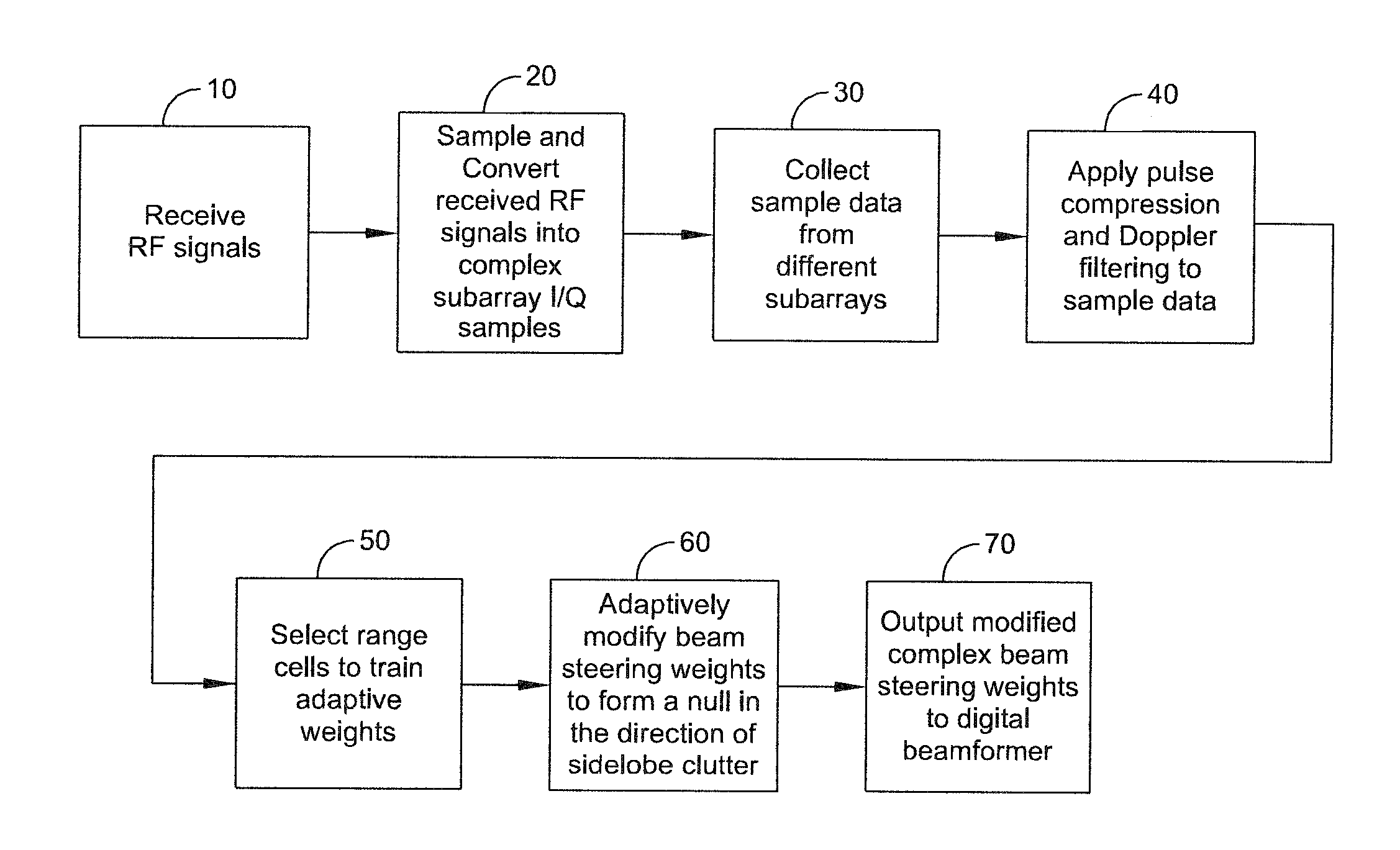
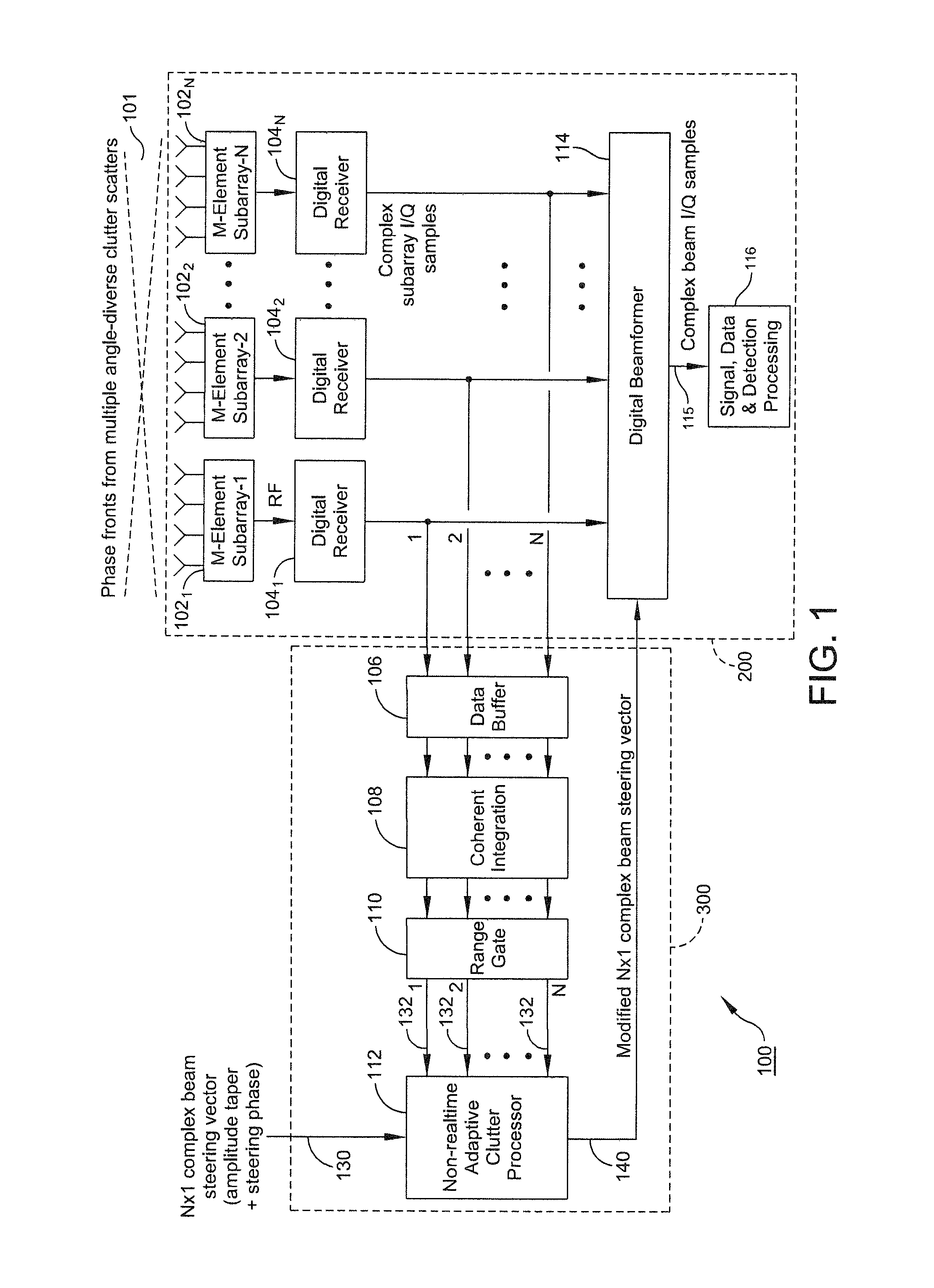
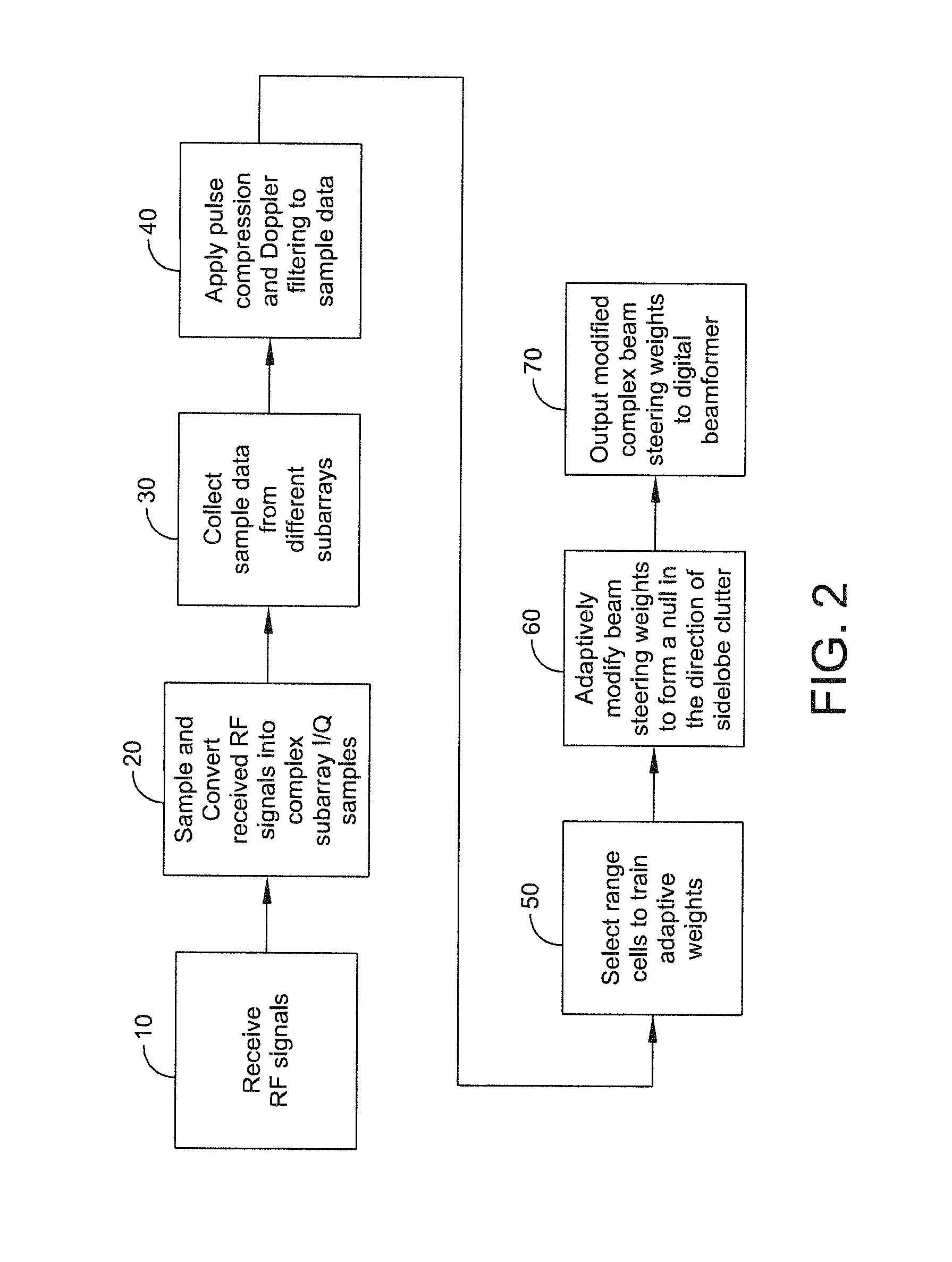
[0012]The present disclosure teaches a method of providing to a beamformer a modified complex beam steering vector that includes the steps of collecting subarray I / Q (inphase / quadrature phase) samples from a plurality of subarrays receiving clutter, performing coherent integration of the subarray I / Q samples to increase the clutter-to-noise ratio, adaptively modifying a complex beam steering vector to form a null in the direction of the received clutter, and outputting to a beamformer the modified comple...


PUM


Abstract

A system and method of providing to a beamformer a modified complex beam steering vector includes collecting subarray I/Q samples from a plurality of subarrays receiving clutter, performing coherent integration of the subarray I/Q samples to increase the CNR, adaptively modifying a complex beam steering vector to form a null in the direction of the received clutter, and outputting to a beamformer the modified complex beam steering vector. The beamformer receives complex I/Q data samples representing a radar signal containing near-horizon clutter and applies the modified beam steering vector to generate a beamformed signal having an elevated mainlobe and a spatial sidelobe null in the direction of the received clutter.

Description

FIELD OF THE INVENTION[0001]This invention relates generally to digital beamforming radar systems, and more specifically, to methods and systems for cancelling clutter from the sidelobes of a ground-based radar.BACKGROUND OF THE INVENTION[0002]Ground-based radars receive clutter from many sources. Typical sources of clutter include terrain clutter, vehicle clutter, and volume clutter, by way of example only. Conventional cancellation techniques for cancelling clutter include Doppler processing and non-adaptive or deterministic spatial nulling. Such cancellation techniques, however, introduce into the system undesirable traits and characteristics that limit their utility.[0003]For example, Doppler processing is typically applied to all beam positions that contain clutter, including lower beam positions contaminated by surface and near-surface clutter through their mainlobes and sidelobes, as well as upper beam positions contaminated by surface and near-surface clutter through their s...

Claims


Application Information

Patent Timeline
IPC IPC(8): G01S13/52G01S7/28G01S7/288H01Q3/26
CPCG01S7/2813H01Q3/2611G01S2007/2886G01S7/023G01S13/28G01S13/42G01S13/5244G01S7/2886
Inventor WASIEWICZ, RICHARDSTOCKMANN, PETER H.
Owner LOCKHEED MARTIN CORP
Why Eureka
Try Eureka