Vision system camera with mount for multiple lens types

Active Publication Date: 2015-02-03
COGNEX CORP
View PDF36 Cites 13 Cited by
  • Summary
  • Abstract
  • Description
  • Claims
  • Application Information

AI Technical Summary

Problems solved by technology

While programs can be readily adapted for a particular vision system task, it is more of a challenge to adapt the system's physical package to that task.
In addition, the cost of the lens and / or the available space for mounting the vision system can drive the choice of lens.

Method used


Image

  • Vision system camera with mount for multiple lens types
  • Vision system camera with mount for multiple lens types
  • Vision system camera with mount for multiple lens types

Examples


Embodiment Construction

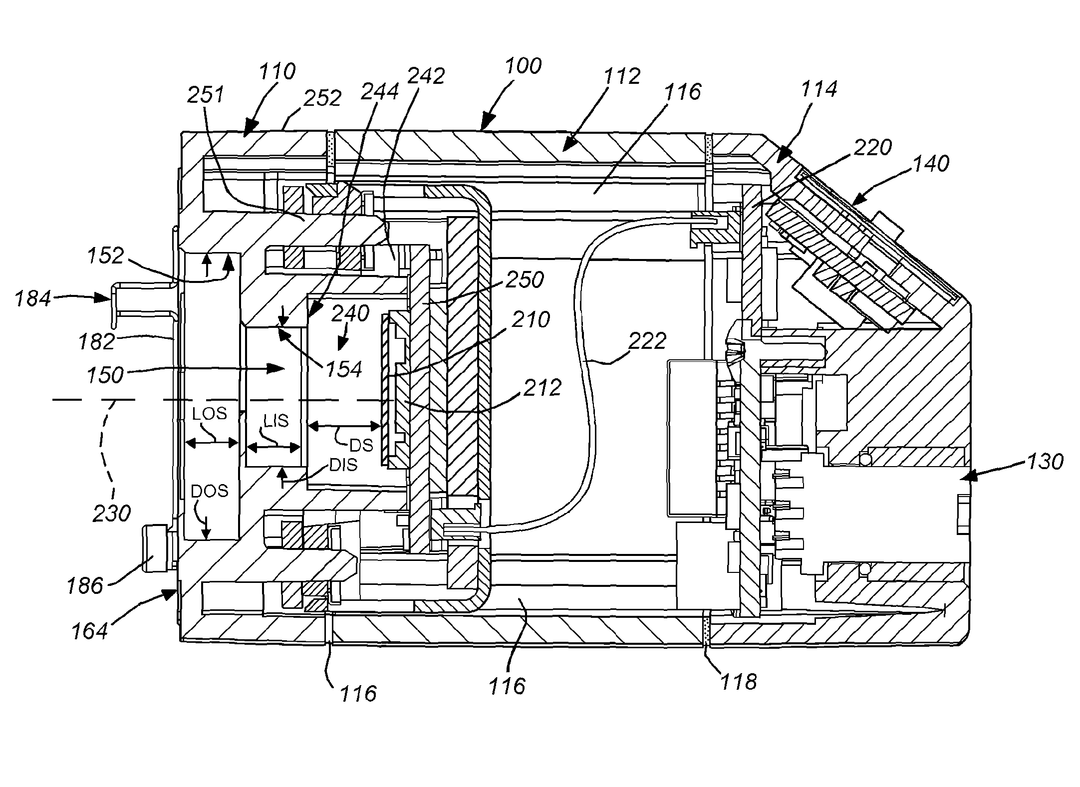
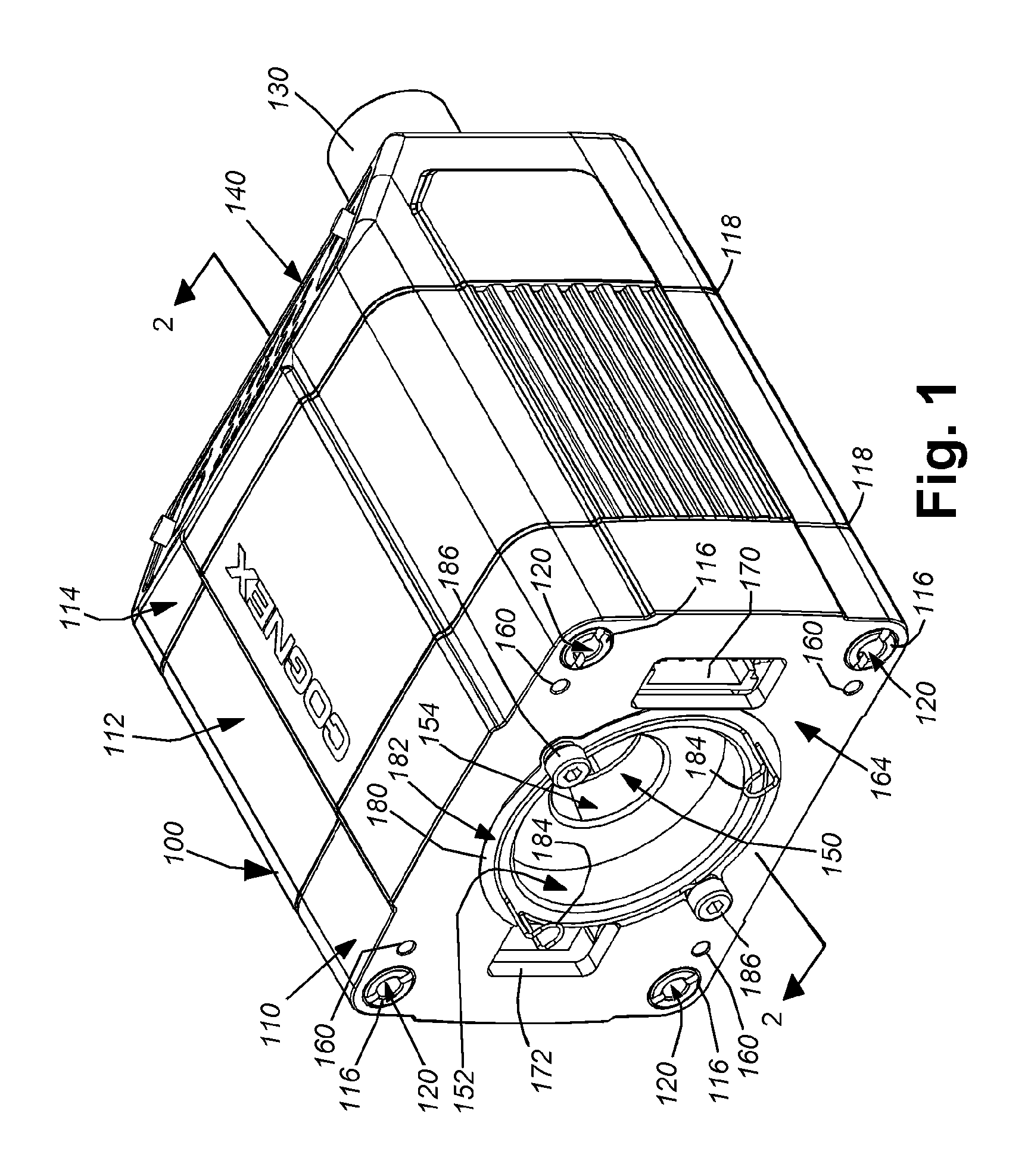
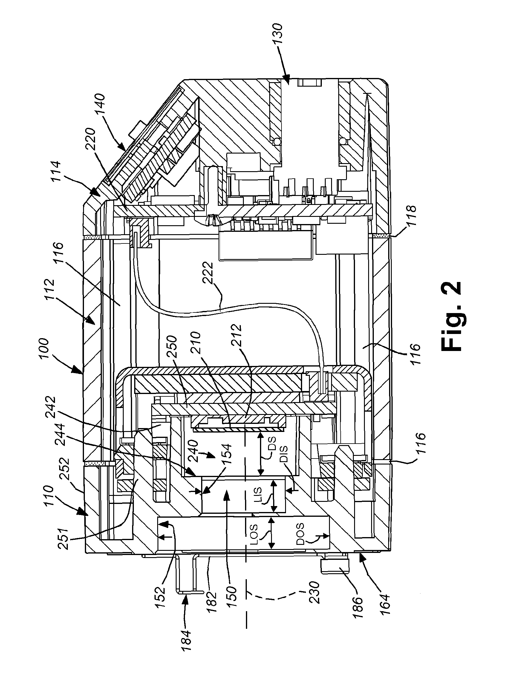
[0021]With reference to FIGS. 1 and 2, a vision system that includes an external package or “housing”100 is shown in detail. The housing 100 can be constructed from polymer, metal, composite or a variety of materials in accordance with ordinary skill. In an embodiment, it consists of a front plate section 110, a main body section 112 and a rear section 114. The front plate section (or “front plate”) 110 is joined to the main body and rear sections using four threaded bolts 116 that are seated within wells in the front plate 110, and that engage threaded holes in the rear section, thereby compressing the three sections together against gaskets 118 that seal the housing against infiltration of moisture and other environmental agents. The construction of the housing is highly variable in alternate embodiments. For example, the housing can be constructed with an integrated or unitary rear and main body or a unitary front plate and main body. Likewise, other fastening techniques can be e...


PUM


Abstract

This invention provides a vision system housing having a front plate assembly that accommodates a plurality of lens mount types. The front plate includes a central aperture that is located at a predetermined axial (camera axis) distance from a plane of an image sensor. The aperture is stepped from a wider diameter adjacent to the front to a narrower diameter more adjacent to the sensor. This arrangement enables threaded mounting of a plurality of lens mount types, for example M12 and C-Mount. The exterior (front) surface of the front plate includes threaded holes and a removable spring clip arrangement constructed to accommodate a liquid lens positioned over the aperture with an associated lens assembly mounted within the aperture and in optical communication with the liquid lens. The lens is operated using an electrical connection provided by a cable that interconnects with a multi-pin socket positioned on the front plate.

Description

FIELD OF THE INVENTION[0001]This invention relates to vision system cameras and more particularly to lens mounts for vision system cameras.BACKGROUND OF THE INVENTION[0002]Vision systems that perform measurement, inspection, alignment of objects and / or decoding of symbology (e.g. bar codes) are used in a wide range of applications and industries. These systems are based around the use of an image sensor, which acquires images (typically grayscale or color, and in one, two or three dimensions) of the subject or object, and processes these acquired images using an on-board or interconnected vision system processor. The processor generally includes both processing hardware and non-transitory computer-readable program instructions that perform one or more vision system processes to generate a desired output based upon the image's processed information. This image information is typically provided within an array of image pixels each having various colors and / or intensities. In the examp...

Claims


Application Information

Patent Timeline
Patent Type & Authority Patents(United States)
IPC IPC(8): H04N5/225G02B3/14G02B7/14G02B26/00G03B17/02G03B17/14
CPCG02B7/14G03B17/02G02B3/14G02B26/005G03B17/14H04N23/55H04N23/51H04N23/54G02B7/022
Inventor NUNNINK, LAURENS
Owner COGNEX CORP
Why Eureka
Try Eureka