
Remote vehicle control system and method

a vehicle control and remote control technology, applied in the field of remote vehicle control systems and methods, can solve the problems that the goal of force multiplication and the effect of increasing operator capability have not been fully realized, and achieve the effect of increasing operator situational awareness

Active Publication Date: 2015-02-10
FLIR DETECTION
View PDF11 Cites 6 Cited by
  • Summary
  • Abstract
  • Description
  • Claims
  • Application Information

AI Technical Summary

Benefits of technology

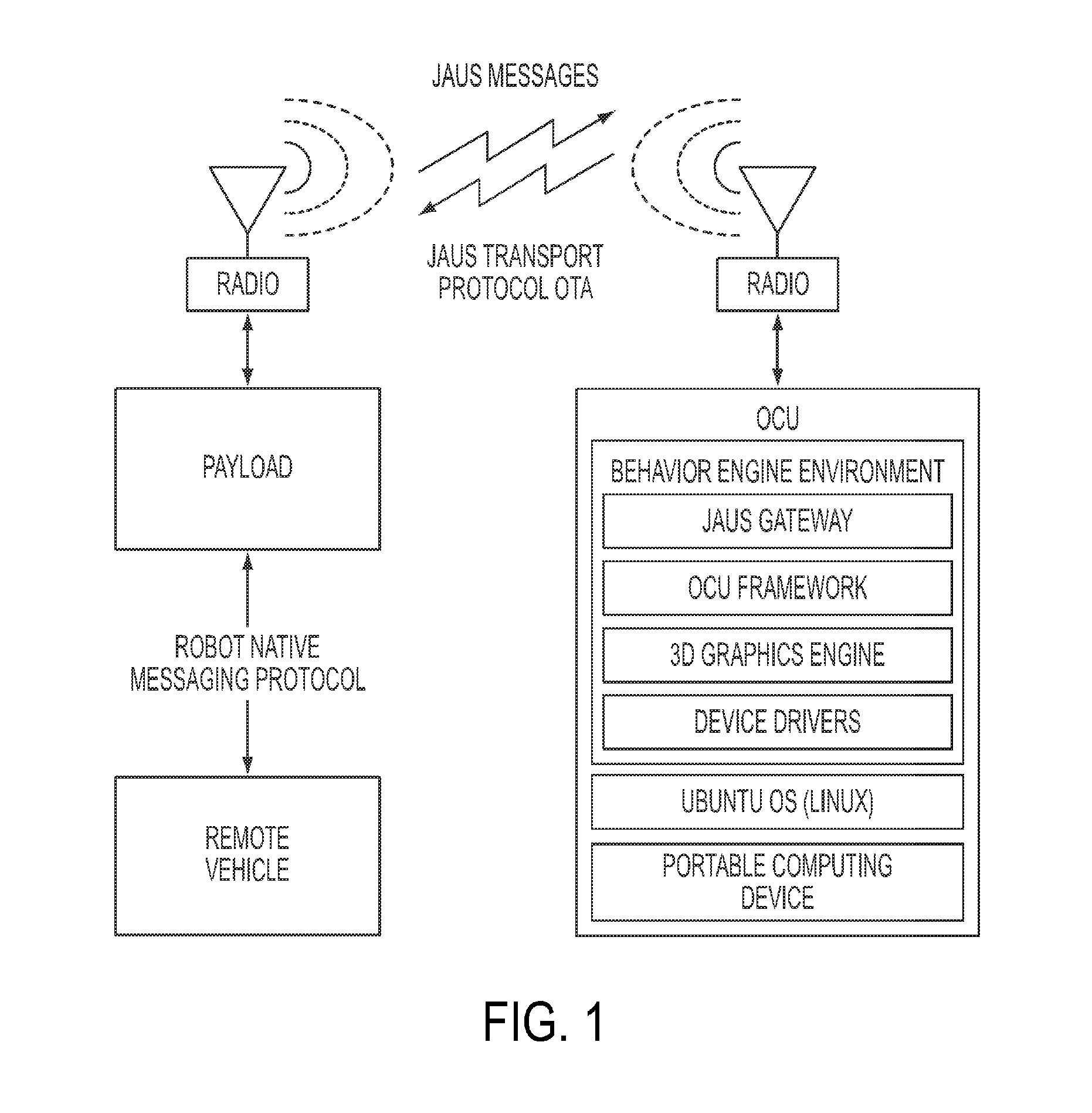
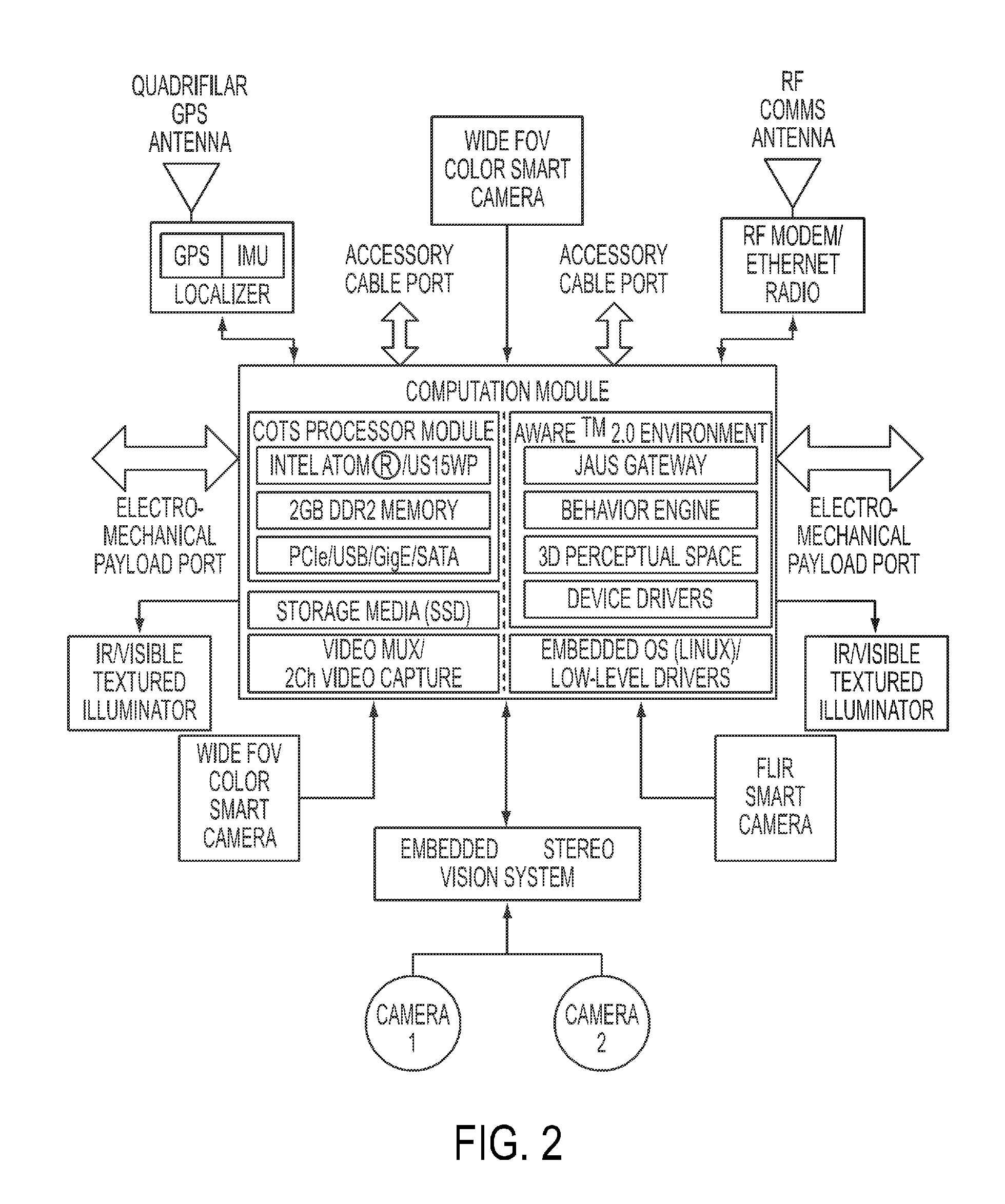
The present patent describes a system that improves the operator's ability to control a remote vehicle by providing a point-and-click interface and a payload attached to the vehicle. The payload includes an integrated sensor suite including GPS, IMU, stereo vision camera, and range sensor. The system can also include smart cameras, illuminators, and supporting electronics. The computational module receives data from the GPS, IMU, stereo vision camera, and range sensor and provides 3D local perceptual space data to a high-performance database that fuses localization sensor data and ranging sensor data. The system also includes a behavior engine that provides kinodynamic, real-time motion planning that accounts for the dynamics and kinematics of the remote vehicle. The method allows the operator to select a part of the remote vehicle representation and command the vehicle by selecting a command on the display. The system can also provide a map display with a 3D local perceptual space display. The technical effects of the system include improved situational awareness, control, and safety for remote vehicle operators.

Problems solved by technology

The goals of force multiplication and increased operator capability have arguably not been fully realized due to the lack of autonomy in fielded robotic systems.

Method used


Image

  • Remote vehicle control system and method
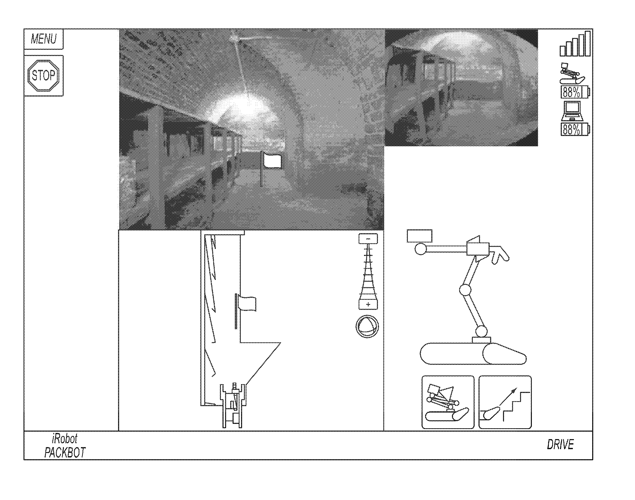
  • Remote vehicle control system and method
  • Remote vehicle control system and method

Examples


Embodiment Construction

[0023]Reference will now be made in detail to exemplary embodiments of the present teachings, examples of which are illustrated in the accompanying drawings. Wherever possible, the same reference numbers will be used throughout the drawings to refer to the same or like parts.

[0024]The present teachings provide a payload capable of facilitating supervisory control of a remote vehicle used, for example, for surveillance, mapping, and explosive ordnance disposal (EOD) missions. The present teachings also provide an appropriately-designed map-based “point-and-click” operator control unit (OCU) application facilitating enhanced, shared situational awareness and seamless access to a supervisory control interface. The remote vehicle can comprise, for example, an iRobot® Packbot® or other remote vehicle platform. In certain embodiments of the present teachings, a pan / tilt mechanism can be employed for mounting the payload to the remote vehicle chassis, to allow the payload to pan and tilt i...


PUM


Abstract

A system increases an operator's situational awareness while the operator controls a remote vehicle. The system comprises an operator control unit having a point-and-click interface configured to allow the operator to view an environment surrounding the remote vehicle and control the remote vehicle, and a payload attached to the remote vehicle and in communication with at least one of the remote vehicle and the operator control unit. The payload comprises an integrated sensor suite including GPS, an inertial measurement unit, a stereo vision camera, and a range sensor, and a computational module receiving data from the GPS, the inertial measurement unit, the stereo vision camera, and the range sensor and providing data to a CPU including at least one of an autonomous behavior and a semi-autonomous behavior that utilize data from the integrated sensor suite.

Description

[0001]This patent application claims priority to U.S. Provisional Patent Application No. 61 / 334,167, filed May 12, 2011, titled Remote Vehicle Control System and Method, the disclosure of which is incorporated by reference herein in its entirety.INTRODUCTION[0002]The present teachings relate to a system and method for increasing remote vehicle operator effectiveness and situational awareness. The present teachings relate more specifically to a system comprising an operator control unit (OCU), a payload, and customized OCU applications that increase remote vehicle operator effectiveness and situational awareness.BACKGROUND[0003]A compelling argument for military robotics is the ability of remote vehicles to multiply the effective force or operational capability of an operator while simultaneously limiting the operator's exposure to safety risks during hazardous missions. The goals of force multiplication and increased operator capability have arguably not been fully realized due to t...

Claims


Application Information

Patent Timeline
Patent Type & Authority Patents(United States)
IPC IPC(8): G06F19/00G05B15/00G05B19/00G05D1/00
CPCG05D1/0038G05D2201/0209G05D1/0016G06F3/04815G06F3/04817G06F3/0488G06F17/00G05D1/0011G01C21/26
Inventor ALLIS, DANIELPACK, ROBERT TODD
Owner FLIR DETECTION
Learn More