
Method for detecting abnormalities in a cryptographic circuit protected by differential logic, and circuit for implementing said method

a cryptographic circuit and anomaly detection technology, applied in the direction of instruments, liquid/fluent solid measurement, power supply for data processing, etc., can solve the problems of inability to detect anomalies in cryptographic circuits protected by differential logic, complex calculations necessary for system security, and inability to detect anomalies in cryptographic circuits

Active Publication Date: 2015-02-10
INST MINES TELECOM
View PDF17 Cites 3 Cited by
  • Summary
  • Abstract
  • Description
  • Claims
  • Application Information

AI Technical Summary

Benefits of technology

This invention uses a special technology called differential logic to protect circuits from attacks. The technology can detect any type of disturbance in a circuit, including attacks that may not be easily observed. This makes it easier to identify and address any potential vulnerabilities in a circuit.

Problems solved by technology

In general, encryption methods involve complex calculations necessary for systems security.
This complexity does not pose any particular problems to computers but it constitutes a drawback in the case of mass-market devices not comprising high calculation power, in general controlled by low-cost microprocessors.
Electronic devices exhibit inevitable imperfections related to the inherent properties of the laws of electricity.
Thus, cryptographic systems which are secure from the mathematical point of view may be attacked by utilizing the imperfections of the physical systems implementing the algorithm.
Moreover, any electrical current flowing in a conductor engenders an electromagnetic field, measurement of which can give rise to attacks identical in principle to attacks pertaining to electrical consumption, notably by DPA.
Finally, so-called active attacks, or fault injection attacks, disturb the operation of systems so as to utilize the false results to retrieve the system's secrets.
Fault injection attacks have, hitherto, and very paradoxically, been considered to be expensive, and therefore accessible in practice solely to financially strong suspicious organizations.
One of the drawbacks of this solution is that it involves an additional cost due to the reproduction of the calculation block or blocks or else to the insertion of a consistency checking module based on verification of invariants.

Method used


Image

  • Method for detecting abnormalities in a cryptographic circuit protected by differential logic, and circuit for implementing said method
  • Method for detecting abnormalities in a cryptographic circuit protected by differential logic, and circuit for implementing said method
  • Method for detecting abnormalities in a cryptographic circuit protected by differential logic, and circuit for implementing said method

Examples


Embodiment Construction

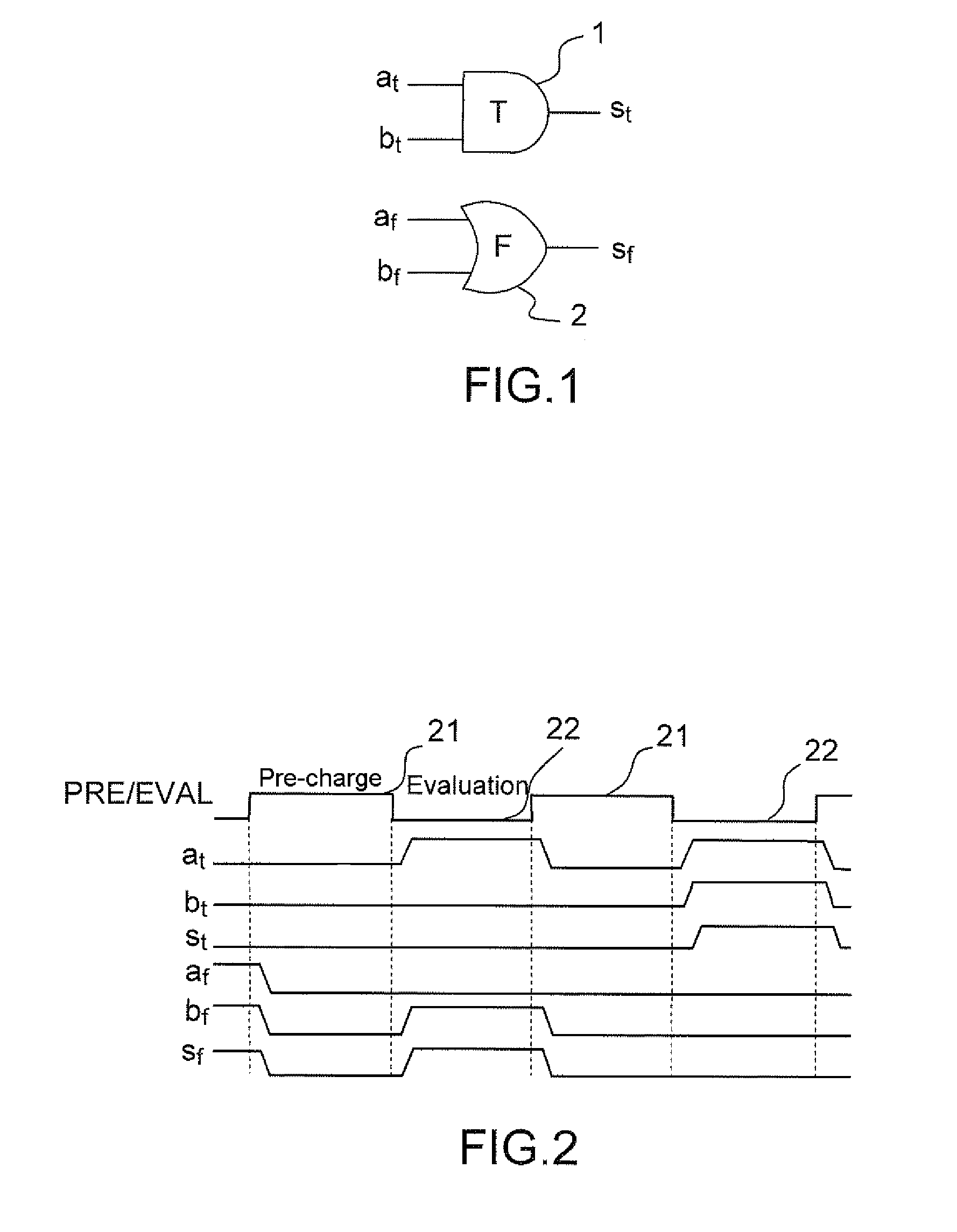
[0047]FIG. 1 presents an “AND” gate 1, 2 in WDDL logic (Wave Dynamic Differential Logic) as an exemplary illustration of the principle of differential logic. The latter is composed of two dual logic networks 1, 2, operating under complementary logic. The example of WDDL logic is used in the subsequent description, but the principle of the invention applies to other types of differential logic, such as for example MDPL logic (Masked Dual-rail Pre-charge Logic). In addition to the duality of the calculation networks, a differential-logic calculation is performed as claimed in two distinct phases: a pre-charge phase and an evaluation phase.

[0048]The data are represented in dual rail, each logic variable a being formed of a pair of signals (at, af) coded in the following manner:[0049](0, 0) for the quiescent state during the pre-charge phase: the value of a is not defined, it is denoted Ω;[0050](1, 0) is an active state during the evaluation phase where a=1;[0051](0, 1) is the other act...


PUM


Abstract

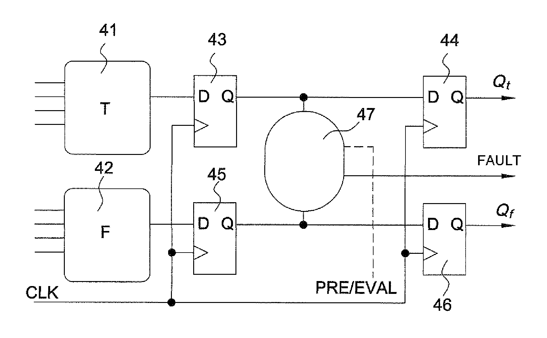
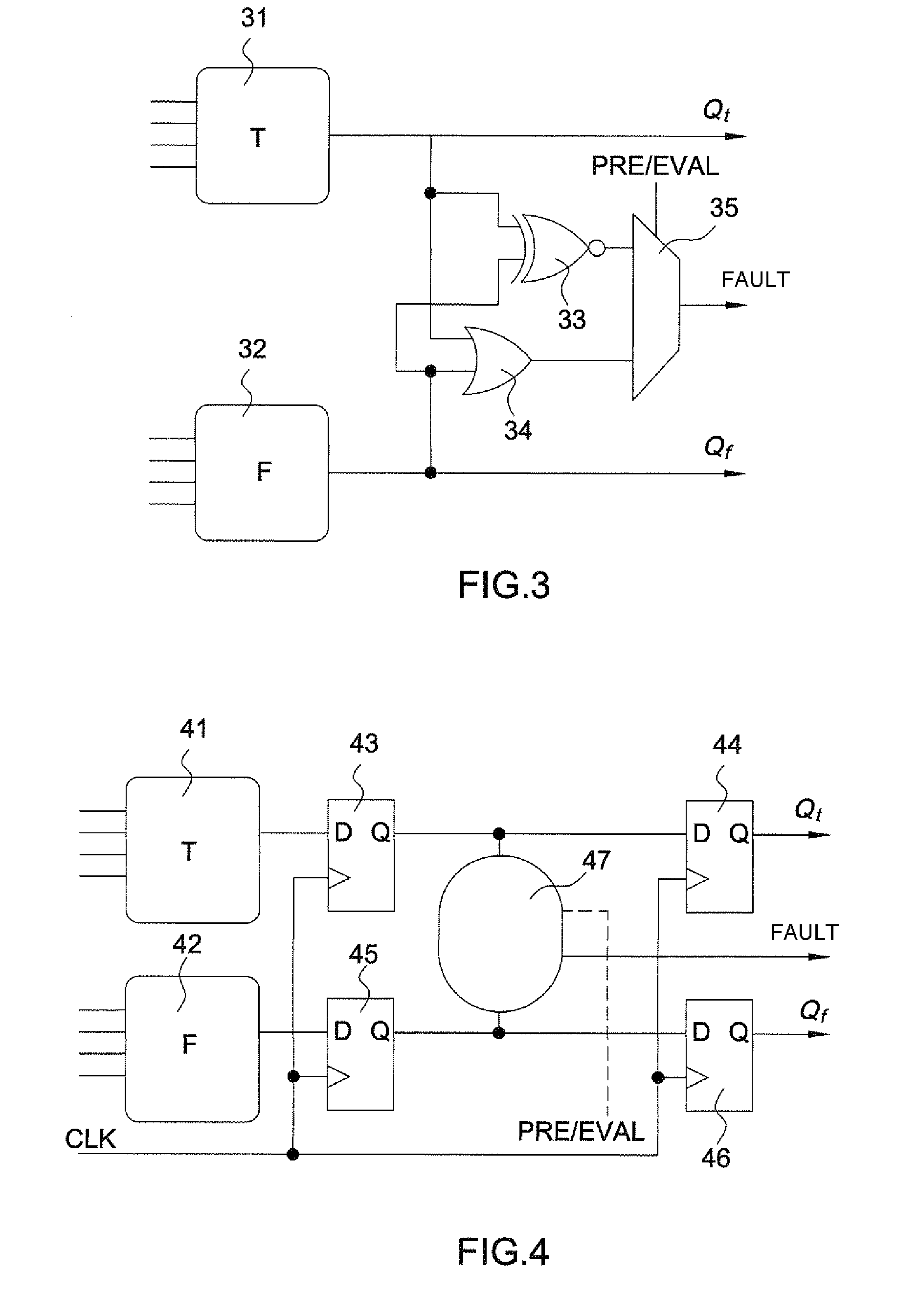
In a method for detecting anomalies in a circuit protected by differential logic and which processes logic variables represented by a pair of components, a first network of cells carrying out logic functions on the first component of said pairs, a second network of dual cells operating in complementary logic on the second component, the logic functions being carried out by each pair of cells in a pre-charge phase placing the variables in a known state on input to the cells and followed by an evaluation phase where a calculation is performed by the cells, the method includes detecting an anomaly by at least one non-consistent state.

Description

CROSS-REFERENCE TO RELATED APPLICATIONS[0001]This application is a National Stage of International patent application PCT / EP2009 / 059886, filed on Jul 30, 2009, which claims priority to foreign French patent application No. FR 08 55537, filed on Aug. 12, 2008, the disclosures of which are incorporated by reference in their entirety.FIELD OF THE INVENTION[0002]The invention relates to a method and a circuit for detecting anomalies in a cryptography circuit protected by differential logic.[0003]It is applied notably to the field of the protection of cryptography circuits against attacks by fault injection.BACKGROUND OF THE INVENTION[0004]The aim of cryptography is notably to protect:[0005]either the secrecy of information by means of encryption and its dual operation, decryption;[0006]or only its integrity, by the operations of signature and signature verification.[0007]Cryptography uses mathematical methods that are secure, in the sense that in the current state of published knowledge...

Claims


Application Information

Patent Timeline
Patent Type & Authority Patents(United States)
IPC IPC(8): G06F21/00G06F21/55G06F21/75
CPCG06F21/558G06F21/75G06F21/755G06F21/55G06F21/602
Inventor DANGER, JEAN-LUCGUILLEY, SYLVAINFLAMENT, FLORENT
Owner INST MINES TELECOM
Learn More