Perimeter-wrapped mattress and method of manufacture

a mattress and perimeter edge technology, applied in the field of mattresses, can solve the problems of forming a dense uncomfortable ridge around the perimeter edge of the mattress, flattening the mattress, and failing to provide a sturdy sitting edg

Active Publication Date: 2015-02-17
PRANASLEEP
View PDF22 Cites 7 Cited by
  • Summary
  • Abstract
  • Description
  • Claims
  • Application Information

AI Technical Summary

Benefits of technology

[0008]The primary object of the present invention is to provide a mattress constructed using a method and system that eliminates the need for conventional foam encasements.

Problems solved by technology

However, such conventional foam encasements are typically two to four inches wide and are constructed out of a polyurethane foam having a density greater than that of the typically latex foam core, thereby creating a dense uncomfortable ridge around the perimeter edge of the mattress.
In addition, polyurethane foam commonly breaks down over time, thereby becoming softer and failing to provide a sturdy sitting edge.
An even further problem with foam encasements is that the foam is flexible, thereby allowing the foam core to spread under a user's weight, thereby flattening the mattress.

Method used


Image

  • Perimeter-wrapped mattress and method of manufacture
  • Perimeter-wrapped mattress and method of manufacture
  • Perimeter-wrapped mattress and method of manufacture

Examples


Embodiment Construction

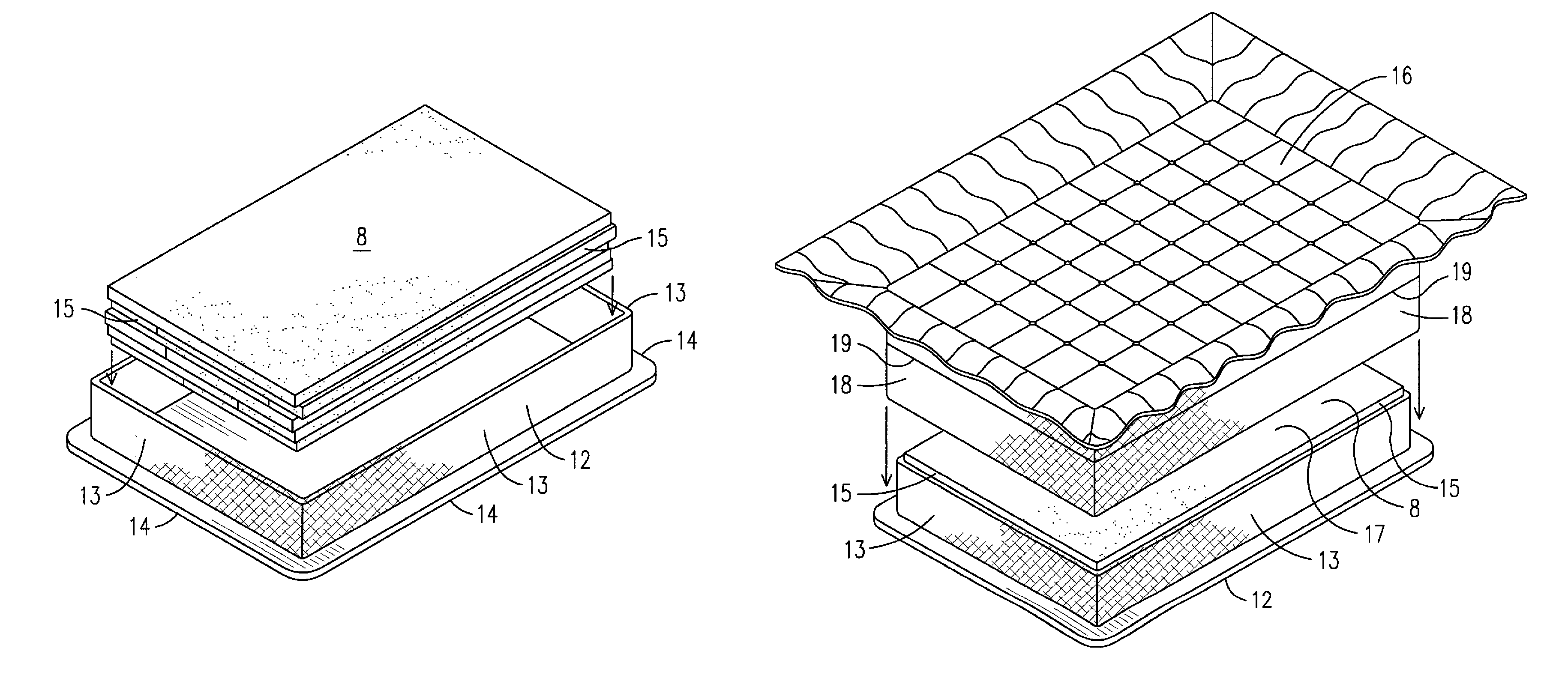
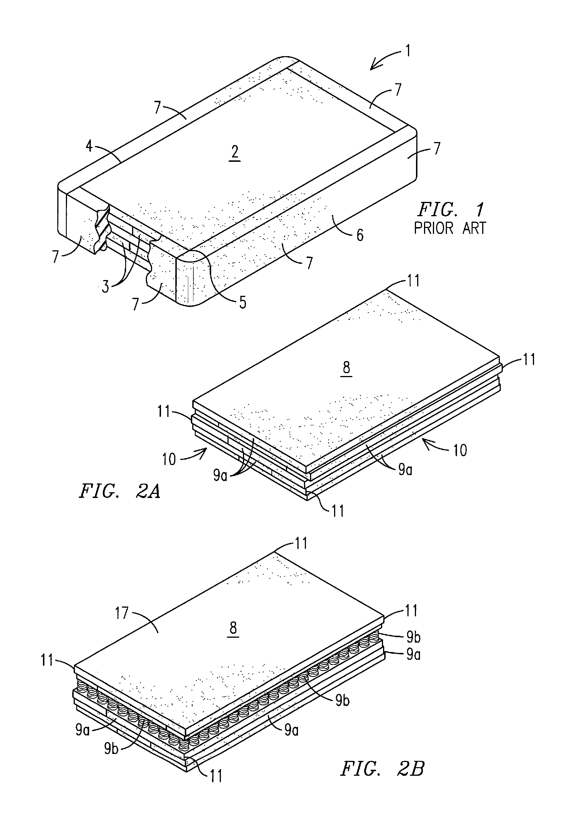
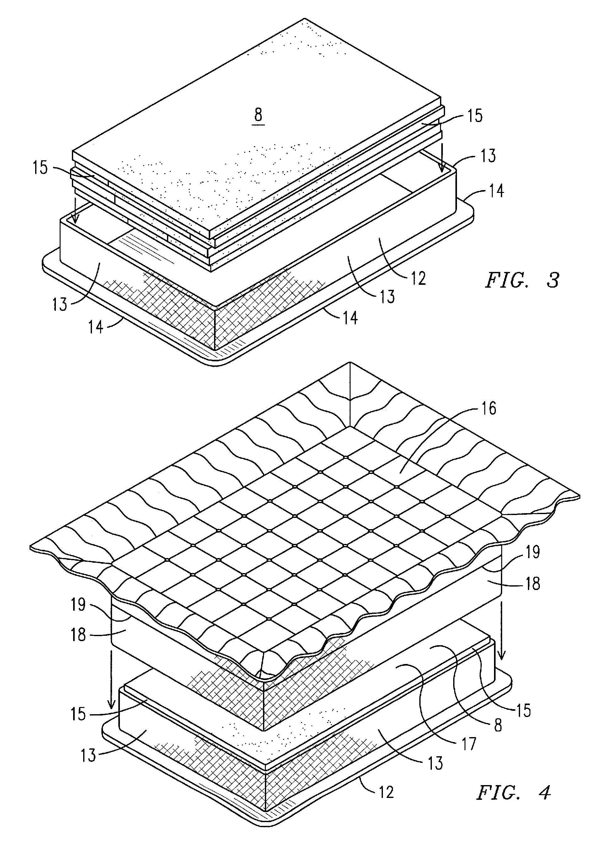
[0027]For purposes of describing the preferred embodiment, the terminology used in reference to the numbered accessories in the drawings is as follows:[0028]1. conventional foam mattress[0029]2. foam core[0030]3. layer of foam[0031]4. edge of foam core[0032]5. corner of foam core[0033]6. foam encasement[0034]7. foam panel[0035]8. foam core[0036]9a. layer of foam[0037]9b. micro-coil spring layer[0038]10. edge of foam core[0039]11. corner of foam core[0040]12. bottom cover[0041]13. bottom flange[0042]14. perimeter of bottom cover[0043]15. side wall of foam core[0044]16. top cover[0045]17. upper surface of foam core[0046]18. top flange[0047]19. perimeter of top cover[0048]20. staple[0049]21. non-woven strip of fabric[0050]22. mattress[0051]23. outer surface of top flange[0052]24. adhesive[0053]25. first end of non-woven strip of fabric[0054]26. second end of non-woven strip of fabric[0055]27. side cover panels

[0056]With reference to FIG. 1, a perspective top partial cutaway view of a c...


PUM

PropertyMeasurementUnit
perimeteraaaaaaaaaa
pressureaaaaaaaaaa
buoyancyaaaaaaaaaa

Abstract

A mattress (22) having a foam core (8) completely extends to the perimeter edges of the mattress wherein side walls (15) of the foam core are compressed inward and held in place using a preferably non-woven strip of fabric (21) or similar non-elastic or non-stretchable material that is wrapped around the side walls of the foam core. A method of wrapping the foam core allows corners (5) of the foam core to be formed under the inward pressure of the non-woven fabric, thereby creating a strong perimeter for the mattress that prevents outward pressure against the sidewalls created by the downward pressure of an individual lying on the mattress from flattening of the mattress by providing more upward pushback against the individual. An optional layer of micro-coil springs (2a) may be located within the foam core to provide more buoyancy and springiness in the mattress.

Description

CROSS REFERENCE TO RELATED APPLICATION[0001]This application claims the benefit of U.S. Provisional Patent Application No. 61 / 559,994, filed Nov. 15, 2011. The patent application identified above is incorporated herein by reference in its entirety to provide continuity of disclosure.FIELD OF THE INVENTION[0002]This invention relates to mattresses, more particularly, a mattress constructed of foam which extends all of the way to the outer perimeter edge of the mattress and is wrapped with a non-elastic or a non-stretchable material, such as a non-woven cloth, and an optional layer of micro-coil springs to provide more buoyancy and springiness in the mattress.BACKGROUND OF THE INVENTION[0003]Foam mattresses are designed for pressure management. When an individual lies on a foam mattress, the foam should distribute the individual's body weight evenly across the entire sleeping surface to reduce uncomfortable pressure points. Foam mattresses are typically constructed using multiple laye...

Claims


Application Information

Patent Timeline
Patent Type & Authority Patents(United States)
IPC IPC(8): A47C27/15A47C27/00
CPCA47C27/002A47C27/15Y10T29/481Y10T29/486
Inventor SCHILLER, STEPHEN J.SAMMARTANO, LUCIEN
Owner PRANASLEEP
Why Eureka
Try Eureka