Light guides for vehicles

a technology for vehicles and light guides, applied in fixed installations, lighting and heating apparatuses, instruments, etc., can solve problems such as unsatisfactory brightness maxima, and achieve the effects of low manufacturing cost and effort, high luminance values, and large brightness maxima

Active Publication Date: 2015-02-17
HELLA KG HUECK & CO
View PDF9 Cites 4 Cited by
  • Summary
  • Abstract
  • Description
  • Claims
  • Application Information

AI Technical Summary

Benefits of technology

[0006]The particular advantage of the invention is, that high luminance values are avoided in the section for the coupling-in of light, so that a homogeneous lighting of the main section of the light guide can be achieved. This is achieved without significantly influencing a radiation characteristic of the light guide in the main section. Also, the defocusing element according to the invention allows a swirling and spatial mixing of the light beams even before the light reaches the main section of the light guide, without photometric or efficiency losses being noted. Large brightness maxima are avoided in the main section as well as in the section for the coupling-in of light. In particular, the invention does also allow the use of RGB-light diodes as a light source, wherein the colors red, green and blue are optimally mixed for the generation of white light in the section for the coupling-in of light. Furthermore, the defocusing element can be formed with relatively little manufacturing cost and effort.
[0007]According to a preferred embodiment of the invention, the defocusing element comprises a widened part connecting to the surface coupling the light in, and a straight part extending between the widened part and the main section. Advantageously, an undesirable focusing of the light beams is avoided here, the straight part of the defocusing element serving the guiding and provision of the light for the main section. In the defocusing element embodied by this means, the coupled-in light receives the opportunity to spread further into the available space and to mix, so that it can meet the element for coupling-out element of the main section with a uniform luminance. The widened part can for example be embodied by means of a free form contour or a conical contour. By these means, the focusing of the light beams is avoided.
[0008]According to a preferred embodiment of the invention, the defocusing element has a defocusing, i.e. light dispersive outer surface which achieves an improved swirling and spatial mixing of the light beams.
[0009]If the light guide has a rod-shaped embodiment, high luminance values in the section for the coupling-in of light or in the main section can be avoided by the use of a conical widened part and a cylindrical straight part.

Problems solved by technology

However, a focusing of the coupled-in light, namely in the focal line, does also occur, so that undesirable brightness maxima occur within the main section of the light guide.

Method used


Image

  • Light guides for vehicles
  • Light guides for vehicles
  • Light guides for vehicles

Examples


Embodiment Construction

[0016]In the following detailed description numerous specific details are set forth in order to provide a thorough understanding of the invention. However, it will be understood by those skilled in the art that the present invention may be practiced without these specific details. For example, the invention is not limited in scope to the particular type of industry application depicted in the figures. In other instances, well-known methods, procedures, and components have not been described in detail so as not to obscure the present invention.

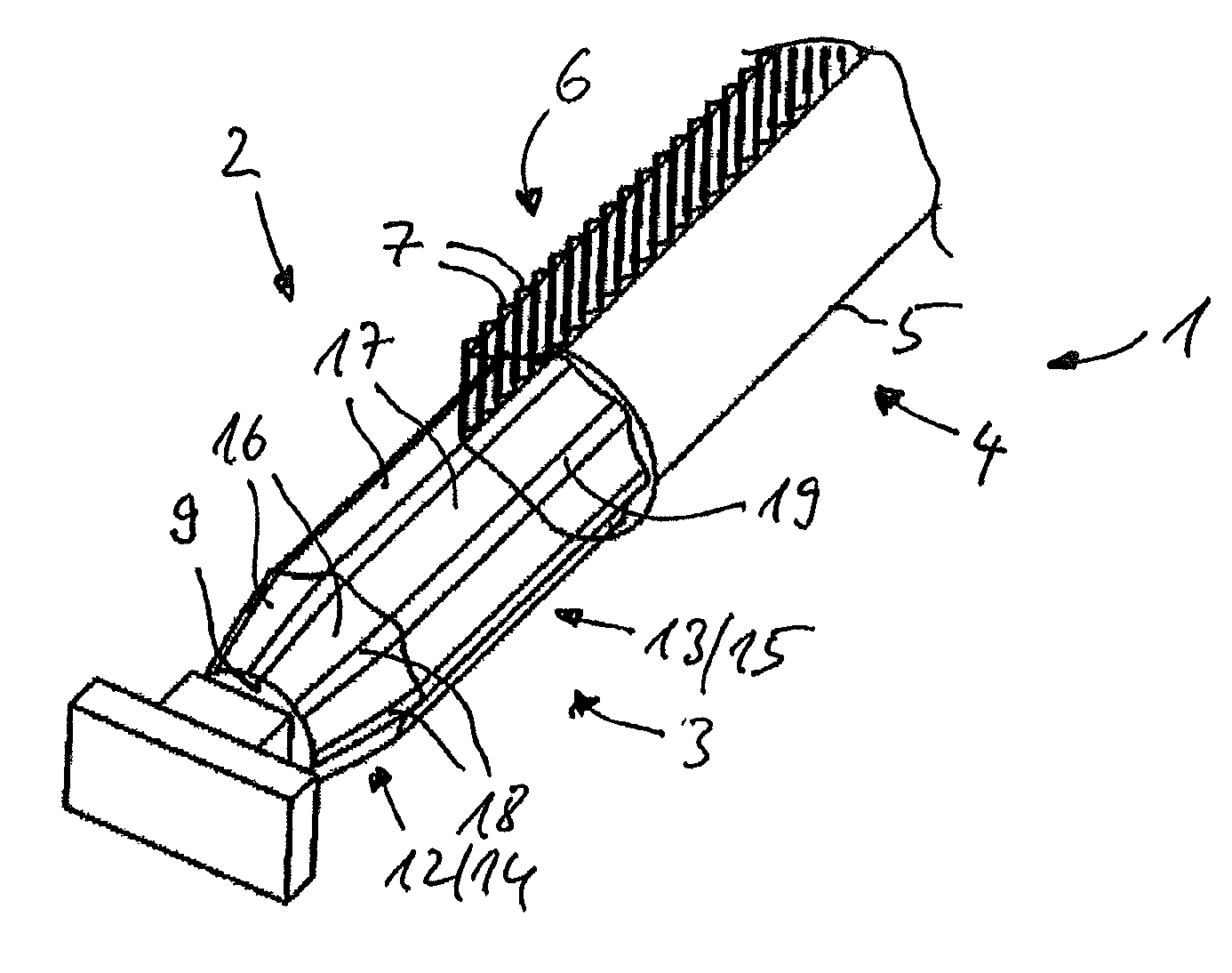
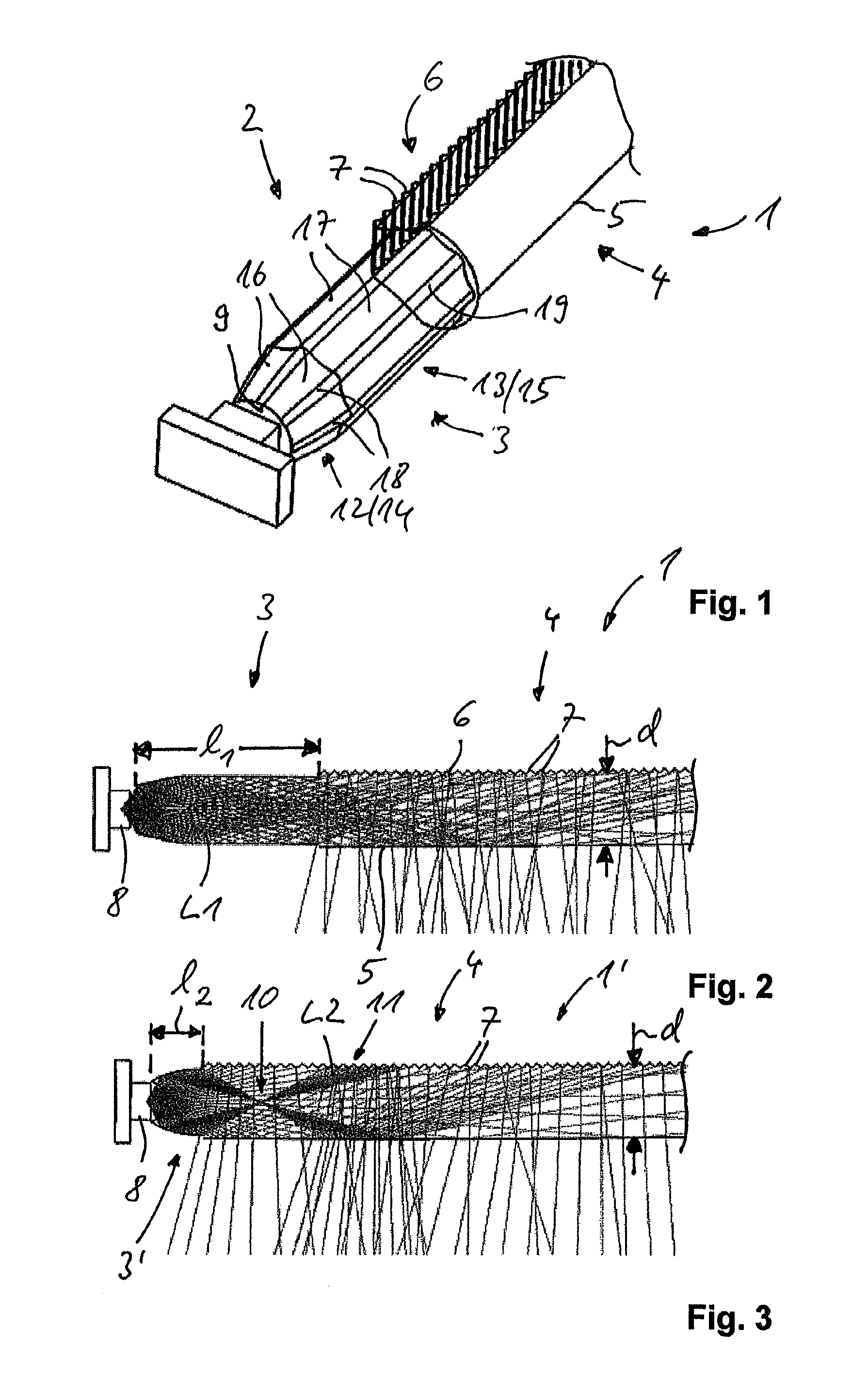
[0017]A light guide according to the invention can be used as signal lamp for vehicles in the rear or front area, for example as daytime running light or marker light. Alternatively, the light guide according to the invention can also be used for the lighting of operating elements or the contour illumination of doors or instrument packs in the passenger compartment.

[0018]The light guide according to the invention can be embodied two-dimensional...


PUM


Abstract

A light guide for vehicles includes a light coupling section for the coupling of light into a first end and / or a second end of the light guide, with a main section having a front side for the coupling out of light and a back extending between the first end and the second end of the light guide and comprising elements for coupling-out for the deflection of the coupled-in light toward the front side, wherein the section for the coupling-in of light is embodied as a defocusing element situated between a surface coupling the light in and the main section.

Description

CROSS REFERENCE[0001]This application claims priority to German Patent Application No. 10 2012 108855.1, filed Sep. 20, 2012.TECHNICAL FIELD OF THE INVENTION[0002]The invention relates to a light guide for vehicles with a light coupling section for the coupling of light into a first end and / or a second end of the light guide, with a main section having a front side for the coupling out of light and a back extending between the first end and the second end of the light guide and comprising elements for coupling out for the deflection of the coupled-in light toward the front side.BACKGROUND OF THE INVENTION[0003]From DE 10 2006 038 759 A1, a light guide for vehicles is known, having a light coupling section for the coupling of light into a light guide and a main section for the distribution and coupling-out of the light along an extension direction of the light guide. On one hand, the main section has a front side, on which the coupled-in light is coupled out into the environment. On ...

Claims


Application Information

Patent Timeline
Patent Type & Authority Patents(United States)
IPC IPC(8): G02B6/26B60Q1/00F21S8/10F21V8/00F21W107/10
CPCG02B6/26B60Q1/0011G02B6/0006G02B6/002F21S48/215F21S48/2237F21S48/2268F21S48/2287G02B6/0038F21S43/14F21S43/237F21S43/245F21S43/247
Inventor BUNGENSTOCK, CARMEN
Owner HELLA KG HUECK & CO
Why Eureka
Try Eureka